CRUISE CONTROL SYSTEM TERMINALS OF ECU
-
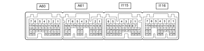
CHECK HYBLID VEHICLE CONTROL ECU
Terminal No.
(Symbol)
Wiring Color Terminal Description Condition Specified Condition A61-28 (ST1-) - I115-6 (E1) G - W-B Stop light signal Power switch on (IG), brake pedal depressed 0 to 1.5 V Power switch on (IG), brake pedal released 11 to 14 V A61-14 (DB2) - I115-6 (E1) Y - W-B Shift position signal Power switch on (IG), shift lever in D or S 11 to 14 V Power switch on (IG), shift lever not in D or S 11 to 14 V A61-26 (DB1) - I115-6 (E1) V - W-B Shift position signal Power switch on (IG), shift lever in D or S 11 to 14 V Power switch on (IG), shift lever not in D or S 0 to 1.5 V I116-3 (BATT) - I115-6 (E1) R - W-B Constant power source Always 11 to 14 V A60-15 (STP) - I115-6 (E1) L - W-B Stop light signal Brake pedal depressed 11 to 14 V Brake pedal released 0 to 1.5 V I116-8 (SFTD) - I115-6 (E1) GR - W-B S shift position switch signal Power switch on (IG), shift lever in S 11 to 14 V Power switch on (IG), shift lever in (-) 0 to 1.5 V I116-9 (SFTU) - I115-6 (E1) LG - W-B S shift position switch signal Power switch on (IG), shift lever in S 11 to 14 V Power switch on (IG), shift lever in (+) 0 to 1.5 V I116-1 (M) - I115-6 (E1) L - W-B S shift position switch signal Power switch on (IG), shift lever in S 11 to 14 V Power switch on (IG), shift lever not in S 0 to 1.5 V I115-28 (CCS) - I115-6 (E1) SB - W-B Cruise control switch circuit Cruise control main switch off 1 MΩ or higher Cruise control main switch on Below 2.5 Ω +RES switch on 236 to 244 Ω -SET switch on 618 to 642 Ω CANCEL switch on 1510 to 1570 Ω