INTAKE MANIFOLD INSTALLATION
PROCEDURE
-
INSTALL INTAKE FLANGE (w/o EGR System)
-
Install a new gasket to the intake manifold.
-
Install the intake flange with the 3 bolts.
- Torque:
- 10 N*m { 102 kgf*cm, 7 ft.*lbf }
-
Install the engine cover joint to the intake flange.
- Torque:
- 10 N*m { 102 kgf*cm, 7 ft.*lbf }
-
-
INSTALL INTAKE MANIFOLD
-
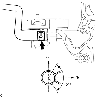
*a Top *b Rear Connect the purge line hose to the intake manifold, and slide the clamp to secure the hose.
Tech Tips
Make sure the hose clamp is oriented as shown in the illustration.
-
Install the vacuum hose to the intake manifold.
-
Install the wiring harness clamp bracket with the bolt.
- Torque:
- 10 N*m { 102 kgf*cm, 7 ft.*lbf }
-
Install a new No. 1 intake manifold to head gasket to the intake manifold.
-
Install the intake manifold to the vehicle.
-
-
INSTALL FUEL DELIVERY PIPE
-
CONNECT FUEL TUBE SUB-ASSEMBLY
-
CONNECT NO. 1 EGR PIPE (w/ EGR System)
-
Install a new gasket to the No. 1 EGR pipe.
Note
Make sure the claws of the gasket face the No. 1 EGR pipe.
-
Temporarily install the No. 1 EGR pipe with the 3 bolts and nut.
-
Tighten the 3 bolts and nut to connect the No. 1 EGR pipe.
- Torque:
- 21 N*m { 214 kgf*cm, 15 ft.*lbf }
-
-
CONNECT INTAKE MANIFOLD
-
Temporarily install the intake manifold with the 6 bolts.
-
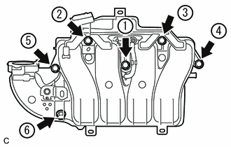
Tighten the 6 bolts in the order shown in the illustration.
- Torque:
- 21 N*m { 214 kgf*cm, 15 ft.*lbf }
-
Connect the No. 2 PCV hose to the intake manifold, and slide the clamp to secure the hose.
-
-
CONNECT ENGINE WIRE
-
Attach the 6 clamps and connect the engine wire.
-
Connect the heated oxygen sensor connector.
-
-
INSTALL MANIFOLD ABSOLUTE PRESSURE SENSOR
-
INSTALL EGR VALVE ASSEMBLY (w/ EGR System)
-
INSTALL AIR CLEANER CASE SUB-ASSEMBLY
-
INSTALL AIR CLEANER FILTER ELEMENT SUB-ASSEMBLY
-
INSTALL OUTER COWL TOP PANEL (for LHD)
-
w/o Performance Rod:
-
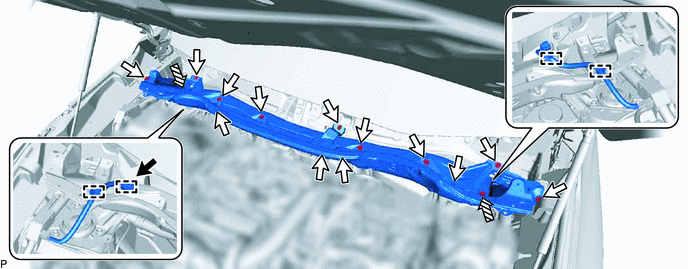
Install the outer cowl top panel with the 13 bolts and 2 nuts.
- Torque:
- for bolt
- 5.5 N*m { 56 kgf*cm, 49 in.*lbf }
- for nut
- 20 N*m { 204 kgf*cm, 15 ft.*lbf }
-
Attach the 4 clamps and connect the wire harness.
-
Connect the connector.

Connector 
Bolt 
Nut - -
-
-
w/ Performance Rod:
-
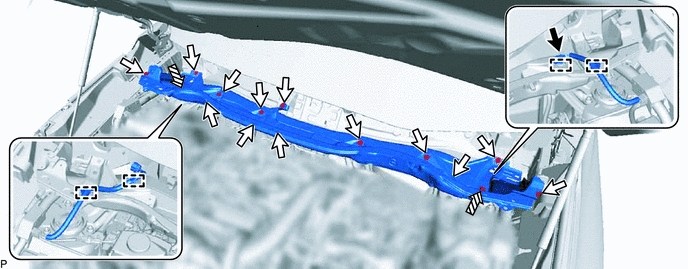
Install the outer cowl top panel with the 13 bolts.
- Torque:
- 5.5 N*m { 56 kgf*cm, 49 in.*lbf }
-
Attach the 4 clamps and connect the wire harness.
-
Connect the connector.
-
-
-
INSTALL OUTER COWL TOP PANEL (for RHD)
-
w/o Performance Rod:
-
Install the outer cowl top panel with the 13 bolts and 2 nuts.
- Torque:
- for bolt
- 5.5 N*m { 56 kgf*cm, 49 in.*lbf }
- for nut
- 20 N*m { 204 kgf*cm, 15 ft.*lbf }
-
Attach the 4 clamps and connect the wire harness.
-
Connect the connector.
Connector Bolt Nut - -
-
-
w/ Performance Rod:
-
Install the outer cowl top panel with the 13 bolts.
- Torque:
- 5.5 N*m { 56 kgf*cm, 49 in.*lbf }
-
Attach the 4 clamps and connect the wire harness.
-
Connect the connector.
-
-
-
INSTALL SUSPENSION TOWER DAMPER (w/ Performance Rod)
-
Install the suspension tower damper with the 2 nuts.
- Torque:
- 20 N*m { 204 kgf*cm, 15 ft.*lbf }
-
-
INSTALL WINDSHIELD WIPER MOTOR ASSEMBLY
-
INSTALL THROTTLE WITH MOTOR BODY ASSEMBLY
-
CONNECT CABLE TO NEGATIVE AUXILIARY BATTERY TERMINAL
Note
When disconnecting the cable, some systems need to be initialized after the cable is reconnected.
-
INSTALL DECK FLOOR BOX LH (w/ Spare Tire)
-
INSTALL REAR DECK FLOOR BOX (w/ Spare Tire)
-
INSTALL NO. 3 DECK BOARD SUB-ASSEMBLY
-
ADD ENGINE COOLANT
-
INSPECT FOR COOLANT LEAK
-
INSPECT FOR FUEL LEAK