INTAKE MANIFOLD REMOVAL
PROCEDURE
-
DISCHARGE FUEL SYSTEM PRESSURE
-
PRECAUTION
Note
After turning the power switch off, waiting time may be required before disconnecting the cable from the auxiliary battery negative (-) terminal. Therefore, make sure to read the disconnecting the cable from the auxiliary battery negative (-) terminal notices before proceeding with work.
-
REMOVE NO. 3 DECK BOARD SUB-ASSEMBLY
-
REMOVE REAR DECK FLOOR BOX (w/ Spare Tire)
-
REMOVE DECK FLOOR BOX LH (w/ Spare Tire)
-
DISCONNECT CABLE FROM NEGATIVE AUXILIARY BATTERY TERMINAL
Note
When disconnecting the cable, some systems need to be initialized after the cable is reconnected.
-
REMOVE THROTTLE WITH MOTOR BODY ASSEMBLY
-
REMOVE WINDSHIELD WIPER MOTOR ASSEMBLY
-
REMOVE SUSPENSION TOWER DAMPER (w/ Performance Rod)
-
Remove the 2 nuts and suspension tower damper.
-
-
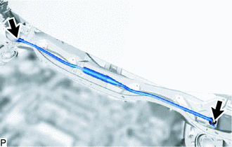
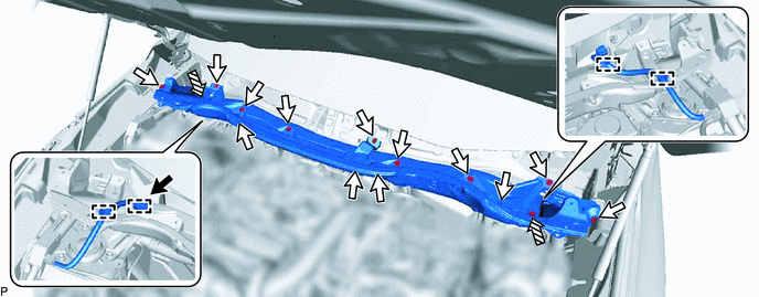
REMOVE OUTER COWL TOP PANEL (for LHD)
-
w/o Performance Rod:
-
Disconnect the connector.
-
Detach the 4 clamps and disconnect the wire harness.
-
Remove the 13 bolts, 2 nuts and outer cowl top panel.

Connector 
Bolt 
Nut - -
-
-
w/ Performance Rod:
-
Disconnect the connector.
-
Detach the 4 clamps and disconnect the wire harness.
-
Remove the 13 bolts and outer cowl top panel.
Connector Bolt
-
-
-
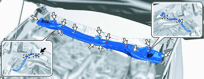
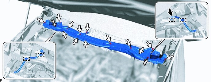
REMOVE OUTER COWL TOP PANEL (for RHD)
-
w/o Performance Rod:
-
Disconnect the connector.
-
Detach the 4 clamps and disconnect the wire harness.
-
Remove the 13 bolts, 2 nuts and outer cowl top panel.
Connector Bolt Nut - -
-
-
w/ Performance Rod:
-
Disconnect the connector.
-
Detach the 4 clamps and disconnect the wire harness.
-
Remove the 13 bolts and outer cowl top panel.
Connector Bolt
-
-
-
REMOVE AIR CLEANER FILTER ELEMENT SUB-ASSEMBLY
-
REMOVE AIR CLEANER CASE SUB-ASSEMBLY
-
REMOVE EGR VALVE ASSEMBLY (w/ EGR System)
-
REMOVE MANIFOLD ABSOLUTE PRESSURE SENSOR
-
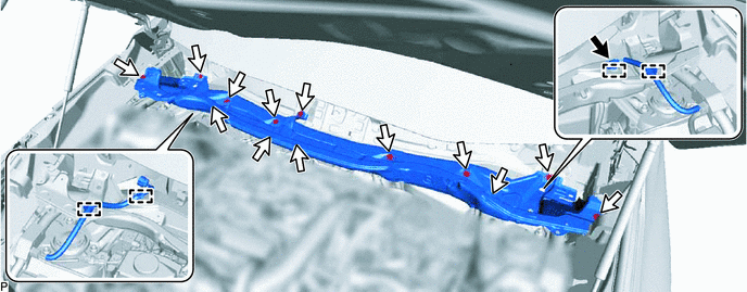
DISCONNECT ENGINE WIRE
-
Disconnect the heated oxygen sensor connector.
-
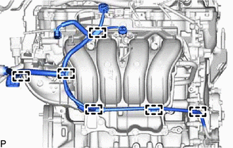
Detach the 6 clamps and disconnect the engine wire.
-
-
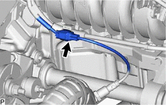
DISCONNECT INTAKE MANIFOLD
-
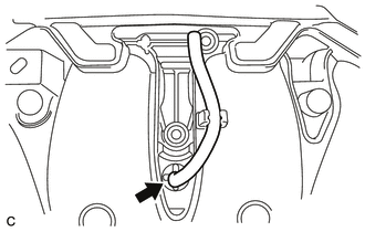
Slide the clamp and disconnect the No. 2 PCV hose from the intake manifold.
-
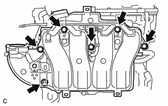
Remove the 6 bolts and disconnect the intake manifold.
-
-
DISCONNECT NO. 1 EGR PIPE (w/ EGR System)
-
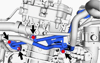
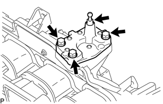
Remove the nut and bolt, and then disconnect the No. 1 EGR pipe from the EGR cooler assembly.
-
Remove the 2 bolts and disconnect the No. 1 EGR pipe.
-
Remove the gasket from the No. 1 EGR pipe.
-
-
DISCONNECT FUEL TUBE SUB-ASSEMBLY
-
REMOVE FUEL DELIVERY PIPE
-
REMOVE INTAKE MANIFOLD
-
Remove the intake manifold from the vehicle.
-
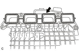
Remove the No. 1 intake manifold to head gasket from the intake manifold.
-
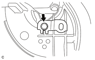
Remove the bolt and wiring harness clamp bracket.
-
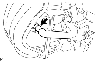
Remove the vacuum hose from the intake manifold.
-
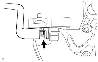
Slide the clamp and disconnect the purge line hose from the intake manifold.
-
-
REMOVE INTAKE FLANGE (w/o EGR System)
-
Remove the engine cover joint from the intake flange.
-
Remove the 3 bolts and intake flange.
-
Remove the gasket from the intake manifold.
-