POWER STEERING SYSTEM(for Manual Tilt and Manual Telescopic Steering Column), Diagnostic DTC:C1524/24, C1555/25
| DTC Code | DTC Name |
|---|---|
| C1524/24 | Motor Circuit Malfunction |
| C1555/25 | Motor Relay Welding Failure |
DESCRIPTION
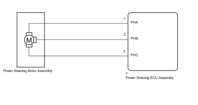
The power steering ECU assembly supplies current to the power steering motor assembly through the motor circuit.
| DTC No. | Detection Item | DTC Detection Condition | Trouble Area | Warning Indicate | Return-to-normal Condition |
|---|---|---|---|---|---|
| C1524/24 | Motor Circuit Malfunction | Short (or open) in motor circuit or abnormal voltage or current in motor circuit |
|
On | Power switch on (IG) again |
| C1555/25 | Motor Relay Welding Failure | Motor relay circuit malfunction |
|
On | Power switch on (IG) again |
WIRING DIAGRAM
CAUTION / NOTICE / HINT
PROCEDURE
-
INSPECT TIGHTENING TORQUE OF MOTOR TERMINAL BOLT
-
Disengage the 4 claws to remove the protector.
-
Check that the motor terminal bolts are tightened to the specified torque.
OK The motor terminal bolts are tightened to the specified torque. Result Proceed to OK NG
NG 
TIGHTEN BOLT TO SPECIFIED TORQUE Click here
OK 
-
-
INSPECT POWER STEERING MOTOR ASSEMBLY
-
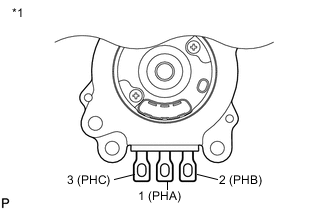
*1 Power Steering Motor Assembly Remove the power steering motor assembly.
-
Measure the resistance according to the value(s) in the table below.
Standard Resistance Tester Connection Condition Specified Condition 1 (PHA) - 2 (PHB) 25°C (77°F) 12.7 to 17.2 mΩ 2 (PHB) - 3 (PHC) 25°C (77°F) 12.7 to 17.2 mΩ 3 (PHC) - 1 (PHA) 25°C (77°F) 12.7 to 17.2 mΩ 1 (PHA) - Motor case Always 10 kΩ or higher 2 (PHB) - Motor case Always 10 kΩ or higher 3 (PHC) - Motor case Always 10 kΩ or higher Result Proceed to OK NG
NG
REPLACE POWER STEERING MOTOR ASSEMBLY Click here
OK
-
-
READ VALUE USING GTS (MOTOR TERMINAL VOLT)
-
Turn the power switch off.
-
Connect the GTS to the DLC3.
-
Turn the power switch on (READY).
-
Turn the GTS on.
-
Enter the following menus: Chassis / EMPS / Data List.
-
Select the items "Motor Terminal Volt (U)", "Motor Terminal Volt (V)" and "Motor Terminal Volt (W)" in the Data List and read the value displayed on the GTS.
Chassis > EMPS > Data ListTester Display Measurement Item Range Normal Condition Diagnostic Note Motor Terminal Volt(U) Motor terminal voltage (A phase) Min.: 0.000 V
Max.: 98.000 V
Power switch on (READY) and steering wheel being turned: Value changes within 4 to 35 V range - Motor Terminal Volt(V) Motor terminal voltage (B phase) Min.: 0.000 V
Max.: 98.000 V
Power switch on (READY) and steering wheel being turned: Value changes within 4 to 35 V range - Motor Terminal Volt(W) Motor terminal voltage (C phase) Min.: 0.000 V
Max.: 98.000 V
Power switch on (READY) and steering wheel being turned: Value changes within 4 to 35 V range -
Chassis > EMPS > Data ListTester Display Motor Terminal Volt(U) Motor Terminal Volt(V) Motor Terminal Volt(W) Result Result Proceed to During steering operation, value changes within 4 to 35 V range. A During steering operation, voltage is not generated. B
A
REPLACE POWER STEERING ECU ASSEMBLY Click here
B
REPLACE POWER STEERING MOTOR ASSEMBLY Click here
-