ELECTRIC PARKING BRAKE SYSTEM Electric Parking Brake System AUTO Function Circuit
DESCRIPTION
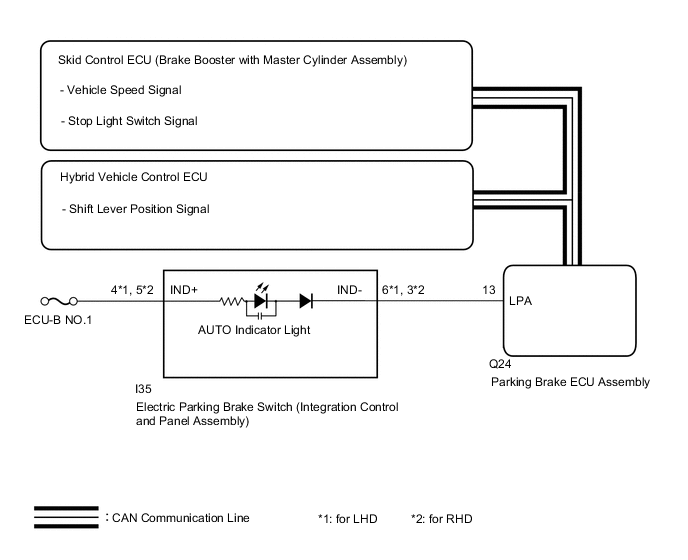
The parking brake ECU assembly receives shift position information from the hybrid vehicle control ECU via CAN communication. Also, the parking brake ECU assembly receives wheel speed information and stop light switch information from the skid control ECU (brake booster with master cylinder assembly).
The electric parking brake system AUTO control (shift-linked) function automatically releases the parking brake when the following conditions are met: 1) Power switch on (IG), 2) brake pedal depressed, and 3) shift lever moved out of P. Also, when the shift lever is moved to P with the vehicle in this condition, the function automatically locks the parking brake.
WIRING DIAGRAM
CAUTION / NOTICE / HINT
Note
-
Before disconnecting connectors or fuses, turn the power switch off and wait 20 seconds or more.
-
When replacing the parking brake ECU assembly, operate the electric parking brake switch (integration control and panel assembly), as the parking brake indicator light (red) blinks when the power switch is first turned on (IG).
PROCEDURE
-
CHECK DTC (CAN COMMUNICATION SYSTEM)
-
Check for DTCs.
Chassis > Electric Parking Brake > Trouble CodesResult Proceed to DTC is not output DTC is output
DTC is output 
GO TO CAN COMMUNICATION SYSTEM Click here
DTC is not output 
-
-
READ VALUE USING GTS (AUTO MODE)
-
Turn the power switch off.
-
Connect the GTS to the DLC3.
-
Turn the power switch on (IG) and the GTS on.
-
Enter the following menus: Chassis / Electric Parking Brake / Data List.
-
Check the values by referring to the table below.
Chassis > Electric Parking Brake > Data ListTester Display Measurement Item Range Normal Condition Auto Mode AUTO (shift-linked) mode permission display ON or OFF ON: AUTO (shift-linked) mode
OFF: Manual mode
Chassis > Electric Parking Brake > Data ListTester Display Auto Mode -
When switching the mode, check that the Data List display turns on and off.
Tech Tips
For details regarding mode switching: Click here
Result Result Proceed to The Data List display does not turn on and off according to mode switching A The Data List display turns on and off according to mode switching B
B 
GO TO STEP 5 Click here
A
-
-
INSPECT ELECTRIC PARKING BRAKE SWITCH (INTEGRATION CONTROL AND PANEL ASSEMBLY)
-
Remove the electric parking brake switch (integration control and panel assembly).
-
Inspect the electric parking brake switch (integration control and panel assembly).
Result Proceed to OK NG
NG
REPLACE INTEGRATION CONTROL AND PANEL ASSEMBLY Click here
OK
-
-
CHECK HARNESS AND CONNECTOR (PARKING BRAKE ECU ASSEMBLY - ELECTRIC PARKING BRAKE SWITCH (INTEGRATION CONTROL AND PANEL ASSEMBLY))
-
Disconnect the I35 electric parking brake switch (integration control and panel assembly) connector.
-
Disconnect the Q24 parking brake ECU assembly connector.
-
Measure the resistance according to the value(s) in the table below.
Standard Resistance for LHD: Tester Connection Condition Specified Condition Q24-20 (LCK1) - I35-9 (LOK1) Always Below 5 Ω Q24-15 (LCK2) - I35-10 (LOK2) Always Below 5 Ω Q24-20 (LCK1) or I35-9 (LOK1) - Body ground Always 10 kΩ or higher Q24-15 (LCK2) or I35-10 (LOK2) - Body ground Always 10 kΩ or higher Q24-19 (REL1) - I35-1 (RLS1) Always Below 5 Ω Q24-16 (REL2) - I35-2 (RLS2) Always Below 5 Ω Q24-19 (REL1) or I35-1 (RLS1) - Body ground Always 10 kΩ or higher Q24-16 (REL2) or I35-2 (RLS2) - Body ground Always 10 kΩ or higher I35-16 (GND1) - Body ground Always Below 5 Ω for RHD: Tester Connection Condition Specified Condition Q24-20 (LCK1) - I35-16 (LOK1) Always Below 5 Ω Q24-15 (LCK2) - I35-15 (LOK2) Always Below 5 Ω Q24-20 (LCK1) or I35-16 (LOK1) - Body ground Always 10 kΩ or higher Q24-15 (LCK2) or I35-15 (LOK2) - Body ground Always 10 kΩ or higher Q24-19 (REL1) - I35-8 (RLS1) Always Below 5 Ω Q24-16 (REL2) - I35-7 (RLS2) Always Below 5 Ω Q24-19 (REL1) or I35-8 (RLS1) - Body ground Always 10 kΩ or higher Q24-16 (REL2) or I35-7 (RLS2) - Body ground Always 10 kΩ or higher I35-9 (GND1) - Body ground Always Below 5 Ω Result Proceed to OK NG
NG
REPAIR OR REPLACE HARNESS OR CONNECTOR
OK
-
-
READ VALUE USING GTS (P / N / R / D POSITION)
-
Turn the power switch off.
-
Connect the GTS to the DLC3.
-
Turn the power switch on (IG) and the GTS on.
-
Enter the following menus: Chassis / Electric Parking Brake / Data List.
-
Check the values by referring to the table below.
Chassis > Electric Parking Brake > Data ListTester Display Measurement Item Range Normal Condition P Position Shift lever position input information display ON or OFF ON: Shift lever is in P
OFF: Shift lever is not in P
N Position Shift lever position input information display ON or OFF ON: Shift lever is in N
OFF: Shift lever is not in N
R Position Shift lever position input information display ON or OFF ON: Shift lever is in R
OFF: Shift lever is not in R
D Position Shift lever position input information display ON or OFF ON: Shift lever is in D or S
OFF: Shift lever is not in D or S
Chassis > Electric Parking Brake > Data ListTester Display P Position N Position R Position D Position -
Check that the Data List display turns on and off according to the shift lever operation.
OK Data List display turns on and off according to shift lever operation. Result Proceed to OK NG
NG
GO TO HYBRID CONTROL SYSTEM Click here
OK
-
-
READ VALUE USING GTS (STOP LIGHT SWITCH)
-
Turn the power switch off.
-
Connect the GTS to the DLC3.
-
Turn the power switch on (IG) and the GTS on.
-
Enter the following menus: Chassis / Electric Parking Brake / Data List.
-
Check the values by referring to the table below.
Chassis > Electric Parking Brake > Data ListTester Display Measurement Item Range Normal Condition Stop Light Switch Stop light switch assembly input information display ON or OFF ON: Brake pedal depressed
OFF: Brake pedal released
Chassis > Electric Parking Brake > Data ListTester Display Stop Light Switch -
Check that the Data List display turns on and off according to the brake pedal operation (depressed and released).
OK On the GTS screen, item changes between ON and OFF according to switch operation. Result Proceed to OK NG
OK
REPLACE PARKING BRAKE ECU ASSEMBLY Click here
NG
GO TO ELECTRONICALLY CONTROLLED BRAKE SYSTEM Click here
-