ELECTRIC PARKING BRAKE SYSTEM, Diagnostic DTC:C13A1/12
| DTC Code | DTC Name |
|---|---|
| C13A1/12 | Short in Power Supply Relay Circuit |
DESCRIPTION
The following DTCs are stored when a malfunction occurs in the parking brake ECU assembly.
| DTC No. | Detection Item | DTC Detection Condition | Trouble Area | Memory | Note |
|---|---|---|---|---|---|
| C13A1/12 | Short in Power Supply Relay Circuit | Both of following conditions are met:
|
|
Yes | An electric parking brake system malfunction is displayed on the multi-information display. |
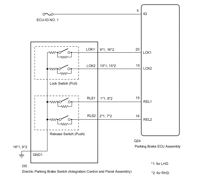
WIRING DIAGRAM
CAUTION / NOTICE / HINT
Note
-
Inspect the fuses for circuits related to this system before performing the following inspection procedure.
-
Before disconnecting connectors or fuses, turn the power switch off and wait 20 seconds or more.
-
When replacing the parking brake ECU assembly, operate the electric parking brake switch (integration control and panel assembly), as the parking brake indicator light (red) blinks when the power switch is first turned on (IG).
PROCEDURE
-
CHECK HARNESS AND CONNECTOR (PARKING BRAKE ECU ASSEMBLY - IG POWER SOURCE CIRCUIT)
-
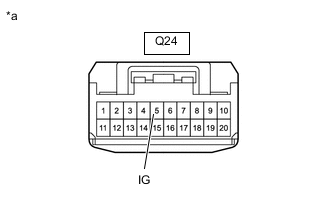
*a Front view of wire harness connector
(to Parking Brake ECU Assembly)
Turn the power switch off.
-
Disconnect the parking brake ECU assembly connector.
-
Measure the voltage according to the value(s) in the table below.
Standard Voltage Tester Connection Switch Condition Specified Condition Q24-5(IG) - Body ground Power switch off Below 2.5 V Result Proceed to OK NG
NG 
REPAIR OR REPLACE HARNESS OR CONNECTOR
OK 
-
-
INSPECT ELECTRIC PARKING BRAKE SWITCH (INTEGRATION CONTROL AND PANEL ASSEMBLY)
-
Remove the electric parking brake switch (integration control and panel assembly).
-
Inspect the electric parking brake switch (integration control and panel assembly).
Result Proceed to OK NG
NG
REPLACE INTEGRATION CONTROL AND PANEL ASSEMBLY Click here
OK
-
-
CHECK HARNESS AND CONNECTOR (PARKING BRAKE ECU ASSEMBLY - ELECTRIC PARKING BRAKE SWITCH (INTEGRATION CONTROL AND PANEL ASSEMBLY))
-
Disconnect the I35 electric parking brake switch (integration control and panel assembly) connector.
-
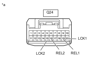
*a Front view of wire harness connector
(to Parking Brake ECU Assembly)
Disconnect the parking brake ECU assembly connector.
-
Measure the resistance according to the value(s) in the table below.
Standard Resistance Tester Connection Condition Specified Condition Q24-20 (LCK1) - Body ground Always 10 kΩ or higher Q24-15 (LCK2) - Body ground Always 10 kΩ or higher Q24-16 (REL2) - Body ground Always 10 kΩ or higher Q24-19 (REL1) - Body ground Always 10 kΩ or higher Result Proceed to OK NG
OK
REPLACE PARKING BRAKE ECU ASSEMBLY Click here
NG
REPAIR OR REPLACE HARNESS OR CONNECTOR
-