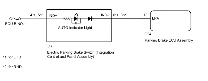
ELECTRIC PARKING BRAKE SYSTEM Electric Parking Brake AUTO Indicator Light Circuit
WIRING DIAGRAM
CAUTION / NOTICE / HINT
Note
-
Inspect the fuses for circuits related to this system before performing the following inspection procedure.
-
Before disconnecting connectors or fuses, turn the power switch off and wait 20 seconds or more.
-
When replacing the parking brake ECU assembly, operate the electric parking brake switch (integration control and panel assembly), as the parking brake indicator light (red) blinks when the power switch is first turned on (IG).
PROCEDURE
-
READ VALUE USING GTS (AUTO MODE)
-
Turn the power switch off.
-
Connect the GTS to the DLC3.
-
Turn the power switch on (IG) and the GTS on.
-
Enter the following menus: Chassis / Electric Parking Brake / Data List.
-
Check the values by referring to the table below.
Chassis > Electric Parking Brake > Data ListTester Display Measurement Item Range Normal Condition Auto Mode AUTO (shift-linked) mode permission display ON or OFF ON: AUTO (shift-linked) mode
OFF: Manual mode
Chassis > Electric Parking Brake > Data ListTester Display Auto Mode -
When switching the mode, check that the Data List display turns on and off.
Tech Tips
For details regarding mode switching: Click here
Result Result Proceed to AUTO indicator light does not illuminate and turn off according to turning Active Test on and off A AUTO indicator light illuminates and turns off according to turning Active Test on and off B
B 
GO TO STEP 5 Click here
A 
-
-
CHECK DTC
-
Check for DTCs.
Chassis > Electric Parking Brake > Trouble CodesResult Proceed to DTC is not output DTC is output
DTC is output 
GO TO DIAGNOSTIC TROUBLE CODE CHART Click here
DTC is not output
-
-
INSPECT ELECTRIC PARKING BRAKE SWITCH (INTEGRATION CONTROL AND PANEL ASSEMBLY)
-
Remove the electric parking brake switch (integration control and panel assembly).
-
Inspect the electric parking brake switch (integration control and panel assembly).
Result Proceed to OK NG
NG
REPLACE INTEGRATION CONTROL AND PANEL ASSEMBLY Click here
OK
-
-
CHECK HARNESS AND CONNECTOR (PARKING BRAKE ECU ASSEMBLY - ELECTRIC PARKING BRAKE SWITCH (INTEGRATION CONTROL AND PANEL ASSEMBLY))
-
Disconnect the I35 electric parking brake switch (integration control and panel assembly) connector.
-
Disconnect the Q24 parking brake ECU assembly connector.
-
Measure the resistance according to the value(s) in the table below.
Standard Resistance for LHD: Tester Connection Condition Specified Condition Q24-20 (LCK1) - I35-9 (LOK1) Always Below 5 Ω Q24-15 (LCK2) - I35-10 (LOK2) Always Below 5 Ω Q24-20 (LCK1) or I35-9 (LOK1) - Body ground Always 10 kΩ or higher Q24-15 (LCK2) or I35-10 (LOK2) - Body ground Always 10 kΩ or higher Q24-19 (REL1) - I35-1 (RLS1) Always Below 5 Ω Q24-16 (REL2) - I35-2 (RLS2) Always Below 5 Ω Q24-19 (REL1) or I35-1 (RLS1) - Body ground Always 10 kΩ or higher Q24-16 (REL2) or I35-2 (RLS2) - Body ground Always 10 kΩ or higher I35-16 (GND1) - Body ground Always Below 5 Ω for RHD: Tester Connection Condition Specified Condition Q24-20 (LCK1) - I35-16 (LOK1) Always Below 5 Ω Q24-15 (LCK2) - I35-15 (LOK2) Always Below 5 Ω Q24-20 (LCK1) or I35-16 (LOK1) - Body ground Always 10 kΩ or higher Q24-15 (LCK2) or I35-15 (LOK2) - Body ground Always 10 kΩ or higher Q24-19 (REL1) - I35-8 (RLS1) Always Below 5 Ω Q24-16 (REL2) - I35-7 (RLS2) Always Below 5 Ω Q24-19 (REL1) or I35-8 (RLS1) - Body ground Always 10 kΩ or higher Q24-16 (REL2) or I35-7 (RLS2) - Body ground Always 10 kΩ or higher I35-9 (GND1) - Body ground Always Below 5 Ω Result Proceed to OK NG
NG
REPAIR OR REPLACE HARNESS OR CONNECTOR
OK
-
-
PERFORM ACTIVE TEST USING GTS (AUTO LIGHT)
-
Turn the power switch off.
-
Connect the GTS to the DLC3.
-
Turn the power switch on (IG) and the GTS on.
-
Enter the following menus: Chassis / Electric Parking Brake / Active Test.
-
Check the values by referring to the table below.
Chassis > Electric Parking Brake > Active TestTester Display Measurement Item Control Range Diagnostic Note Auto Light AUTO indicator light ON or OFF
-
Vehicle stopped
-
Power switch on (IG)
Chassis > Electric Parking Brake > Active TestTester Display Auto Light -
-
When turning the Active Test on and off, check that the AUTO indicator light illuminates and turns off.
Result Result Proceed to AUTO indicator light does not illuminate and turn off according to turning Active Test on and off A AUTO indicator light illuminates and turns off according to turning Active Test on and off B
B
USE SIMULATION METHOD TO CHECK Click here
A
-
-
CHECK HARNESS AND CONNECTOR (AUXILIARY BATTERY - ELECTRIC PARKING BRAKE SWITCH (INTEGRATION CONTROL AND PANEL ASSEMBLY))
-
Turn the power switch off.
-
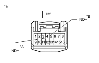
*A for LHD *B for RHD *a Front view of wire harness connector
(to Electric Parking Brake Switch (Integration Control and Panel Assembly))
Disconnect the I35 electric parking brake switch (integration control and panel assembly) connector.
-
Measure the voltage according to the value(s) in the table below.
Standard Voltage for LHD: Tester Connection Condition Specified Condition I35-4 (IND+) - Body ground Always 11 to 14 V for RHD: Tester Connection Condition Specified Condition I35-5 (IND+) - Body ground Always 11 to 14 V Result Proceed to OK NG
NG
REPAIR OR REPLACE HARNESS OR CONNECTOR
OK
-
-
CHECK HARNESS AND CONNECTOR (AUXILIARY BATTERY - PARKING BRAKE ECU ASSEMBLY)
-
Turn the power switch off.
-
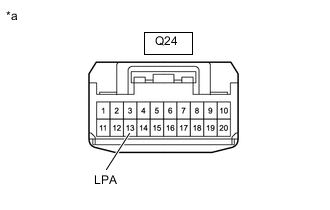
*a Front view of wire harness connector
(to Parking Brake ECU Assembly)
Disconnect the parking brake ECU assembly connector.
-
Measure the voltage according to the value(s) in the table below.
Standard Voltage Tester Connection Condition Specified Condition Q24-13 (LPA) - Body ground Always 9 to 14 V Result Proceed to OK NG
OK
REPLACE PARKING BRAKE ECU ASSEMBLY Click here
NG
-
-
CHECK HARNESS AND CONNECTOR (PARKING BRAKE ECU ASSEMBLY - ELECTRIC PARKING BRAKE SWITCH (INTEGRATION CONTROL AND PANEL ASSEMBLY))
-
Turn the power switch off.
-
Disconnect the Q24 parking brake ECU assembly connector.
-
Disconnect the I35 electric parking brake switch (integration control and panel assembly) connector.
-
Measure the resistance according to the value(s) in the table below.
Standard Resistance for LHD: Tester Connection Condition Specified Condition Q24-13 (LPA) - I35-6 (IND-) Always Below 5 Ω Q24-13 (LPA) or I35-6 (IND-) - Body ground Always 100 kΩ or higher for RHD: Tester Connection Condition Specified Condition Q24-13 (LPA) - I35-3 (IND-) Always Below 5 Ω Q24-13 (LPA) or I35-3 (IND-) - Body ground Always 100 kΩ or higher Result Proceed to OK NG
OK
REPLACE INTEGRATION CONTROL AND PANEL ASSEMBLY Click here
NG
REPAIR OR REPLACE HARNESS OR CONNECTOR
-