ELECTRIC PARKING BRAKE SYSTEM, Diagnostic DTC:C13A7/43
| DTC Code | DTC Name |
|---|---|
| C13A7/43 | Actuator Malfunction |
DESCRIPTION
| DTC No. | Detection Item | DTC Detection Condition | Trouble Area | Memory | Note |
|---|---|---|---|---|---|
| C13A7/43 | Actuator Malfunction | Both of following conditions are met:
|
|
Yes | An electric parking brake system malfunction is displayed on the multi-information display. |
WIRING DIAGRAM
CAUTION / NOTICE / HINT
Note
-
This DTC may be stored when the system changes to pad replacement mode, but this is not a malfunction.
-
This DTC may be stored when the parking brake is forcibly released, but this is not a malfunction.
-
Before disconnecting connectors or fuses, turn the power switch off and wait 20 seconds or more.
-
When replacing the parking brake ECU assembly, operate the electric parking brake switch (integration control and panel assembly), as the parking brake indicator light (red) blinks when the power switch is first turned on (IG).
PROCEDURE
-
CHECK DTC
-
Check if DTCs other than C13A7/43 are output.
Chassis > Electric Parking Brake > Trouble CodesResult Proceed to DTC C13A7/43 is not output DTC C13A7/43 is output
DTC C13A7/43 is output 
GO TO DIAGNOSTIC TROUBLE CODE CHART Click here
DTC C13A7/43 is not output 
-
-
READ VALUE USING GTS (RH ACTUATOR MALFUNCTION(LOCK)/RH ACTUATOR MALFUNCTION(SPIN)/LH ACTUATOR MALFUNCTION(LOCK)/LH ACTUATOR MALFUNCTION(SPIN))
-
Turn the power switch off.
-
Connect the GTS to the DLC3.
-
Turn the power switch on (IG) and the GTS on.
-
Enter the following menus: Chassis / Electric Parking Brake / Data List.
-
Check the values by referring to the table below.
Chassis > Electric Parking Brake > Data ListTester Display Measurement Item Range Normal Condition RH Actuator Malfunction(Lock) Parking brake actuator assembly RH lock detection malfunction details are displayed Detected Malfunction or No Detected Malfunction No Detected Malfunction RH Actuator Malfunction(Spin) Parking brake actuator assembly RH spinning malfunction details are displayed Detected Malfunction or No Detected Malfunction No Detected Malfunction LH Actuator Malfunction(Lock) Parking brake actuator assembly LH lock detection malfunction details are displayed Detected Malfunction or No Detected Malfunction No Detected Malfunction LH Actuator Malfunction(Spin) Parking brake actuator assembly LH spinning malfunction details are displayed Detected Malfunction or No Detected Malfunction No Detected Malfunction
Chassis > Electric Parking Brake > Data ListTester Display RH Actuator Malfunction(Lock) RH Actuator Malfunction(Spin) LH Actuator Malfunction(Lock) LH Actuator Malfunction(Spin) Result Proceed to NEXT
NEXT
-
-
INSPECT PARKING BRAKE WIRE ASSEMBLY NO.1
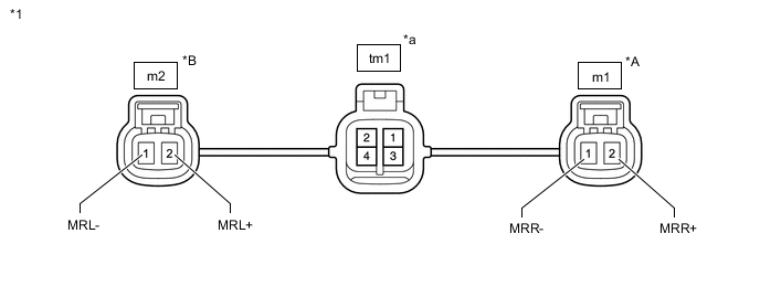
*1 Parking Brake Wire Assembly - - *A RH *B LH *a Male connector - -
-
Remove the parking brake wire assembly.
-
Check the parking brake wire assembly for damage.
OK No damage. Tech Tips
If damaged, there may be a short between the wire harnesses or a short to ground.
-
Inspect the parking brake wire assembly.
Standard Resistance LH Tester Connection Condition Specified Condition tm1 (Male connector)-1 - m2-2 (MRL+) Always Below 1 Ω tm1 (Male connector)-3 - m2-1 (MRL-) Always Below 1 Ω tm1 (Male connector)-1 - m2-1 (MRL-) Always 10 kΩ or higher tm1 (Male connector)-3 - m2-2 (MRL+) Always 10 kΩ or higher tm1 (Male connector)-1 - tm1 (Male connector)-3 Always 10 kΩ or higher tm1 (Male connector)-1 - tm1 (Male connector)-2 Always 10 kΩ or higher tm1 (Male connector)-1 - tm1 (Male connector)-4 Always 10 kΩ or higher tm1 (Male connector)-3 - tm1 (Male connector)-2 Always 10 kΩ or higher tm1 (Male connector)-3 - tm1 (Male connector)-4 Always 10 kΩ or higher RH: Tester Connection Condition Specified Condition tm1 (Male connector)-2 - m1-2 (MRR+) Always Below 1 Ω tm1 (Male connector)-4 - m1-1 (MRR-) Always Below 1 Ω tm1 (Male connector)-2 - m1-1 (MRR-) Always 10 kΩ or higher tm1 (Male connector)-4 - m1-2 (MRR+) Always 10 kΩ or higher tm1 (Male connector)-2 - tm1 (Male connector)-4 Always 10 kΩ or higher tm1 (Male connector)-2 - tm1 (Male connector)-1 Always 10 kΩ or higher tm1 (Male connector)-2 - tm1 (Male connector)-3 Always 10 kΩ or higher tm1 (Male connector)-4 - tm1 (Male connector)-1 Always 10 kΩ or higher tm1 (Male connector)-4 - tm1 (Male connector)-3 Always 10 kΩ or higher Result Proceed to OK NG
NG
REPLACE PARKING BRAKE WIRE ASSEMBLY NO.1 Click here
OK
-
-
CHECK HARNESS AND CONNECTOR (PARKING BRAKE ECU ASSEMBLY - PARKING BRAKE ACTUATOR ASSEMBLY)
-
Turn the power switch off.
-
Make sure the parking brake wire assembly is securely installed.
-
Disconnect the Q25 parking brake ECU assembly connector.
-
Disconnect the m1 and/or m2 parking brake actuator assembly connector.
-
Measure the resistance according to the value(s) in the table below.
Standard Resistance LH Tester Connection Condition Specified Condition Q25-4 (MRL+) - m2-2 (MRL+) Always Below 1 Ω Q25-6 (MRL-) - m2-1 (MRL-) Always Below 1 Ω Q25-4 (MRL+) or m2-2 (MRL+) - Body ground Always 10 kΩ or higher Q25-6 (MRL-) or m2-1 (MRL-) - Body ground Always 10 kΩ or higher RH Tester Connection Condition Specified Condition Q25-1 (MRR+) - m1-2 (MRR+) Always Below 1 Ω Q25-3 (MRR-) - m1-1 (MRR-) Always Below 1 Ω Q25-1 (MRR+) or m1-2 (MRR+) - Body ground Always 10 kΩ or higher Q25-3 (MRR-) or m1-1 (MRR-) - Body ground Always 10 kΩ or higher Result Proceed to OK NG
NG
REPAIR OR REPLACE HARNESS OR CONNECTOR
OK
-
-
INSPECT REAR BRAKE AND PARKING BRAKE ACTUATOR ASSEMBLY
-
Enter rear brake pad replacement mode.
-
Turn the power switch off.
-
Check whether there is a rotation system stuck malfunction or the actuator is spinning.
-
Check whether the parking brake actuator assembly is installed properly to the rear brake caliper and that it is not spinning.
For the parking brake actuator assembly removal procedure: Click here
-
Check whether there is any damage to the rotation transmission part from the parking brake actuator assembly to the rear brake caliper.
-
Inspect the parking brake actuator assembly and check that it operates.
-
Check that the rear brake caliper threaded portion rotates and that the rear disc brake piston can move outward.
Tech Tips
For the check procedures, refer to the parking brake emergency release method when not using the GTS.
Result Proceed to OK NG -
OK
REPLACE PARKING BRAKE ACTUATOR ASSEMBLY Click here
NG
REPAIR OR REPLACE NECESSARY PARTS
-