STEERING COLUMN ASSEMBLY(for Power Tilt and Power Telescopic Steering Column) INSTALLATION
CAUTION / NOTICE / HINT
Note
-
Do not replace the spiral cable with sensor sub-assembly with the battery connected and the power switch on (IG).
-
Do not rotate the spiral cable with sensor sub-assembly when the following conditions are met: 1) The steering wheel is removed, 2) the battery is connected,and 3) the power switch is on (IG).
-
Ensure that the steering wheel is installed and aligned straight when inspecting the steering sensor.
Tech Tips
-
Use the same procedure for RHD and LHD vehicles.
-
The procedure listed below is for LHD vehicles.
PROCEDURE
-
INSTALL NO. 2 STEERING INTERMEDIATE SHAFT ASSEMBLY
-
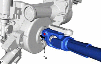
*a Matchmark Align the matchmarks on the No. 2 steering intermediate shaft assembly and electric power steering column sub-assembly.
-
Install the bolt.
- Torque:
- 35.3 N*m { 360 kgf*cm, 26 ft.*lbf }
-
-
INSTALL ELECTRIC POWER STEERING COLUMN SUB-ASSEMBLY
-
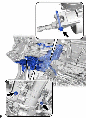
Install the electric power steering column sub-assembly with the bolt and 2 nuts.
- Torque:
- for Bolt
- 36 N*m { 367 kgf*cm, 27 ft.*lbf }
- for Nut
- 21 N*m { 214 kgf*cm, 15 ft.*lbf }
Note
-
Do not damage the 2 bushings.
-
Do not line-up the bolt hole by prying on the collar or bushings. Only install the bolt straight, without applying any force to the bushings.
-
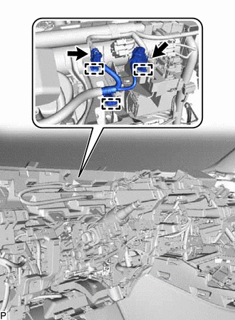
Connect the connectors and attach the 3 clamps.
-
Connect the wire harness with the bolt.
- Torque:
- 8.35 N*m { 85 kgf*cm, 74 in.*lbf }
-
-
INSTALL NO. 1 AIR DUCT
-
Attach the 3 claws to install a new No. 1 air duct.
Note
If the No. 1 air duct is reused, it may fall off or abnormal noise may occur. Therefore, make sure to replace with a new one.
-
-
PLACE FRONT WHEELS FACING STRAIGHT AHEAD
-
CONNECT NO. 2 STEERING INTERMEDIATE SHAFT ASSEMBLY
-
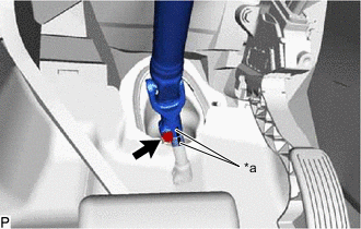
*a Matchmark Align the matchmarks on the No. 2 steering intermediate shaft assembly and steering intermediate shaft assembly.
-
Install the bolt.
- Torque:
- 35.3 N*m { 360 kgf*cm, 26 ft.*lbf }
-
-
INSTALL COLUMN HOLE COVER SILENCER SHEET
-
Install the column hole cover silencer sheet with the 2 clips.
-
Install the floor carpet.
-
-
INSTALL LOWER NO. 1 INSTRUMENT PANEL AIRBAG ASSEMBLY
-
INSTALL UPPER INSTRUMENT PANEL SUB-ASSEMBLY
-
INSTALL COMBINATION SWITCH ASSEMBLY WITH SPIRAL CABLE SUB-ASSEMBLY
-
Attach the 3 claws to install the combination switch assembly with spiral cable sub-assembly to the electric power steering column sub-assembly.
-
Connect the connectors to the combination switch assembly with spiral cable sub-assembly.
-
-
INSTALL UPPER STEERING COLUMN COVER
-
Attach the 4 clips, 3 claws and 2 pins to install the upper steering column cover.
-
-
INSTALL LOWER STEERING COLUMN COVER
-
Attach the 2 claws to install the lower steering column cover.
Note
Do not damage the tilt and telescopic switch.
-
Install the 3 screws.
-
-
FRONT WHEELS FACING STRAIGHT AHEAD
-
ADJUST SPIRAL CABLE
-
INSTALL STEERING WHEEL ASSEMBLY
-
CUSTOMIZE POWER TILT AND POWER TELESCOPIC STEERING COLUMN SYSTEM
-
Reset the auto tilt away function setting to the previous condition by changing the customize parameter.
-
-
PERFORM TORQUE SENSOR ZERO POINT CALIBRATION
-
PERFORM ASSIST MAP WRITING