INVERTER WITH CONVERTER REMOVAL
PROCEDURE
-
PRECAUTION
-
REMOVE SERVICE PLUG GRIP
-
DRAIN COOLANT (for Inverter Coolant)
-
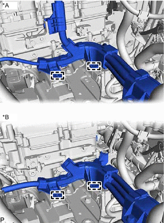
DISCONNECT WIRE HARNESS
-
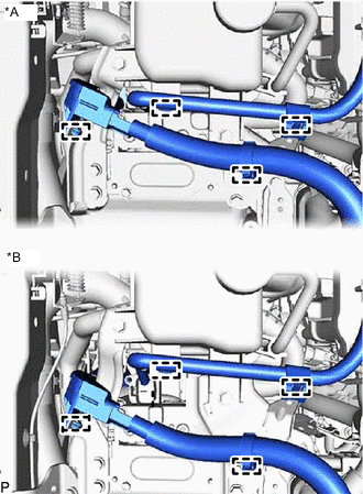
*A for AWD *B for 2WD Disconnect the 4 wire harness clamps from the inverter reserve tank assembly and inverter with converter assembly.
-
-
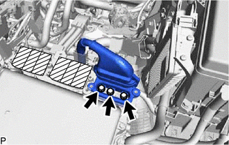
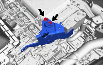
REMOVE INVERTER RESERVE TANK ASSEMBLY
-
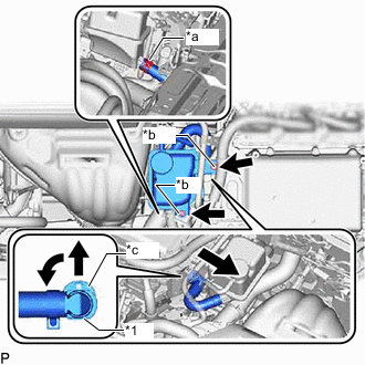
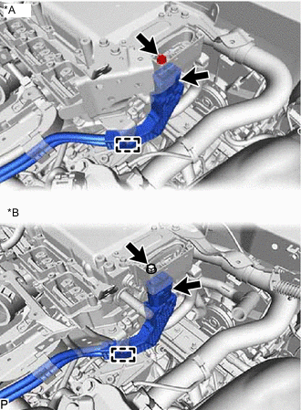
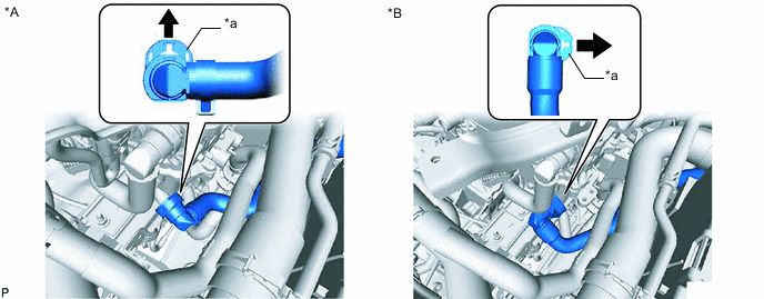
*1 Quick Connector *a Hose Clamp *b Bolt *c Retainer Slide the hose clamp, and disconnect the water hose from the inverter reserve tank assembly.
-
Remove the 2 bolts, and disconnect the inverter reserve tank assembly from the inverter reserve tank bracket.
-
Slide the retainer as shown in the illustration, disconnect the No. 1 inverter cooling hose assembly, and remove the inverter reserve tank assembly.
Note
Cover the disconnected water hose and pipe with a plastic bag and tape to prevent coolant from splattering.
Tech Tips
Turn the quick connector to the left, then release the retainer to prevent it from interfering with the inverter bracket.
-
-
REMOVE NO. 1 INVERTER RESERVE TANK BRACKET (for 2WD)
-
Remove the 2 bolts and No. 1 inverter reserve tank bracket.
-
-
REMOVE CONNECTOR COVER ASSEMBLY
CAUTION:
Be sure to wear insulated gloves.
-
*A for AWD *B for 2WD Using an insulated tool, remove the 2 bolts and connector cover assembly.
Note
-
Pull the connector cover assembly straight up, as a connector is connected to the bottom of the cover.
-
Do not allow any foreign objects or water to enter the inverter with converter assembly.
-
-
-
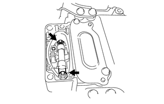
CHECK TERMINAL VOLTAGE
-
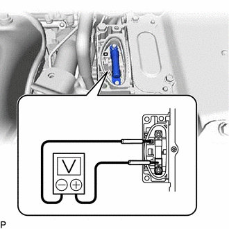
Using a voltmeter, measure the voltage between the terminals of the 2 phase connectors.
Standard voltage 0 V Tech Tips
Use a measuring range of DC 750 V or more on the voltmeter.
-
-
TEMPORARILY INSTALL CONNECTOR COVER ASSEMBLY
-
*A for AWD *B for 2WD Temporarily install the connector cover assembly with the bolt to prevent any foreign objects or water from entering the inverter with converter.
-
-
REMOVE RADIATOR SUPPORT OPENING COVER
-
REMOVE AIR CLEANER CAP SUB-ASSEMBLY
-
REMOVE AIR CLEANER FILTER ELEMENT SUB-ASSEMBLY
-
REMOVE AIR CLEANER CASE SUB-ASSEMBLY
-
REMOVE UPPER INVERTER COVER
CAUTION:
Be sure to wear insulated gloves.
-
*A for AWD *B for 2WD Using an insulated tool, remove the 2 bolts and upper inverter cover (generator cable side).
Note
-
Make sure to pull the upper inverter cover straight up, as a connector is connected to the bottom of the cover.
-
Do not touch the rubber seal of the upper inverter cover.
-
-
-
DISCONNECT GENERATOR CABLE
CAUTION:
Be sure to wear insulated gloves.
-
*A for AWD *B for 2WD Using an insulated tool, remove the 3 bolts.
-
*A for AWD *B for 2WD Disconnect the wire harness clamp and generator cable from the inverter bracket.
Note
-
When disconnecting, do not damage the terminals, connector housing and inverter with converter assembly.
-
Do not touch the connector rubber seal and terminal.
-
Wrap insulation tape around the removed terminals to insulate them.
-
Cover the hole with non-residue tape to prevent entry of foreign matter or water after removing the cable.
-
-
-
REMOVE UPPER INVERTER COVER
CAUTION:
Be sure to wear insulated gloves.
-
*A for AWD *B for 2WD Using an insulated tool, remove the 2 bolts and upper inverter cover (motor cable side).
Note
-
Make sure to pull the upper inverter cover straight up, as a connector is connected to the bottom of the cover.
-
Do not touch the rubber seal of the upper inverter cover.
-
-
-
DISCONNECT MOTOR CABLE
-
*A for AWD *B for 2WD Using an insulated tool, remove the 3 bolts.
-
Disconnect the wire harness clamp and the motor cable from the inverter bracket.
Note
-
When disconnecting, do not damage the terminals, connector housing and inverter with converter assembly.
-
Do not touch the connector rubber seal and terminal.
-
Wrap insulation tape around the removed terminals to insulate them.
-
Cover the hole with non-residue tape to prevent entry of foreign matter or water after removing the cable.
-
-
-
REMOVE UPPER INVERTER COVER (for AWD)
CAUTION:
Be sure to wear insulated gloves.
-
Using an insulated tool, remove the 2 bolts and upper inverter cover (rear motor high-voltage cable side).
Note
-
Make sure to pull the upper inverter cover straight up, as a connector is connected to the bottom of the cover.
-
Do not touch the rubber seal of the upper inverter cover.
-
-
-
REMOVE NO. 2 FRAME WIRE
CAUTION:
Be sure to wear insulated gloves.
-
for AWD:
Using an insulated tool, remove the 3 bolts.
-
*A for AWD *B for 2WD Detach the 2 clamps.
-
for AWD:
Disconnect the wire harness clamp and the No. 2 frame wire (rear motor high-voltage cable side) from the air cleaner bracket.
Note
-
When disconnecting, do not damage the terminals, connector housing and inverter with converter assembly.
-
Do not touch the connector rubber seal and terminal.
-
Wrap insulation tape around the removed terminals to insulate them.
-
Cover the hole with non-residue tape to prevent entry of foreign matter or water after removing the cable.
-
-
-
REMOVE CONNECTOR COVER ASSEMBLY
CAUTION:
Be sure to wear insulated gloves.
-
*A for AWD *B for 2WD Remove the bolt and connector cover assembly.
Note
-
Pull the connector cover assembly straight up, as a connector is connected to the bottom of the cover.
-
Do not allow any foreign objects or water to enter the inverter with converter assembly.
-
-
-
DISCONNECT ENGINE WIRE
CAUTION:
Be sure to wear insulated gloves.
-
*A for AWD *B for 2WD Disconnect the engine wire connector from the inverter with converter assembly.
Note
-
When disconnecting, do not damage the terminals, connector housing and inverter with converter assembly.
-
Do not touch the connector rubber seal and terminal.
-
Wrap insulation tape around the removed terminals to insulate them.
-
Cover the hole with non-residue tape to prevent entry of foreign matter or water after removing the cable.
-
-
-
DISCONNECT NO. 2 FRAME WIRE
CAUTION:
Be sure to wear insulated gloves.
-
*A for AWD *B for 2WD Remove the bolt.
-
Remove the clamp and disconnect the No. 2 frame wire.
Note
-
When disconnecting, do not damage the terminals, connector housing and inverter with converter assembly.
-
Do not touch the connector rubber seal and terminal.
-
Wrap insulation tape around the removed terminals to insulate them.
-
Cover the hole with non-residue tape to prevent entry of foreign matter or water after removing the cable.
-
-
-
TEMPORARILY INSTALL CONNECTOR COVER ASSEMBLY
CAUTION:
Be sure to wear insulated gloves.
-
Temporarily install the connector cover assembly with the bolt to prevent any foreign objects or water from entering the inverter with converter assembly.
-
-
DISCONNECT LOW VOLTAGE CONNECTOR
-
Lift up the lock lever, and disconnect the 3 low voltage connectors.
Note
-
Cover the hole with non-residue tape to prevent entry of foreign matter or water after removing the connector.
-
To prevent damage caused by static electricity, do not touch the terminals of connectors.
-
-
-
DISCONNECT NO. 3 ENGINE ROOM WIRE
-
Remove the relay block cover.
-
Remove the nut from the No. 3 engine room wire.
-
Attach the 2 claws, and disconnect the No. 3 engine room wire from the junction block.
-
-
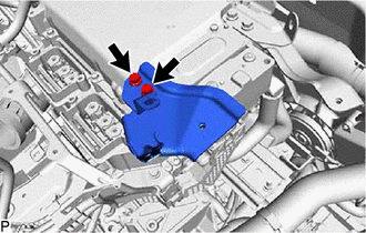
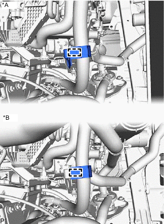
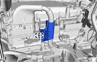
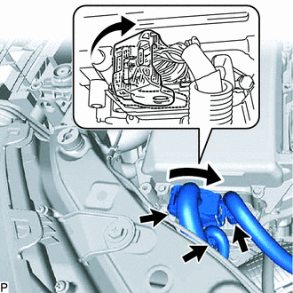
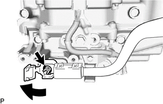
DISCONNECT NO. 2 INVERTER COOLING HOSE ASSEMBLY
-
Slide the retainer in the direction of the arrow shown in the illustration to disconnect the No. 2 inverter cooling hose assembly from the inverter with converter assembly.
*A for AWD *B for 2WD *a Retainer - - -
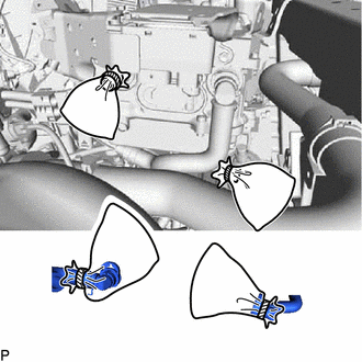
Plug the pipe and the disconnected hose with vinyl tape, etc. or cover the pipe and hose with plastic bags as shown in the illustration, so that foreign matter does not stick to the union or the inside of the connector and to prevent coolant from spilling near the inverter with converter assembly or enter the cooling path.
-
-
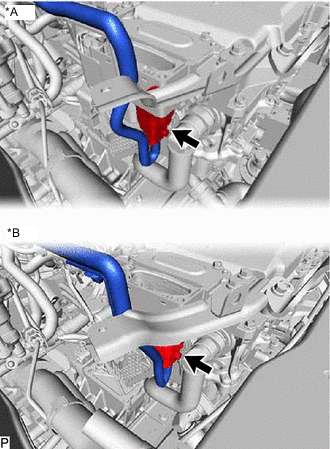
REMOVE INVERTER WITH CONVERTER ASSEMBLY
CAUTION:
Be sure to wear insulated gloves.
-
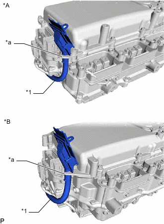
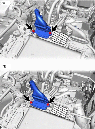
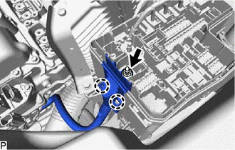
*A for AWD *B for 2WD *1 No. 3 Engine Room Wire *a Hook Temporarily secure the No. 3 engine room wire to the hook on the inverter with converter assembly as shown in the illustration.
-
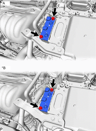
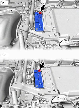
Remove the 2 bolts and No. 6 inverter bracket.
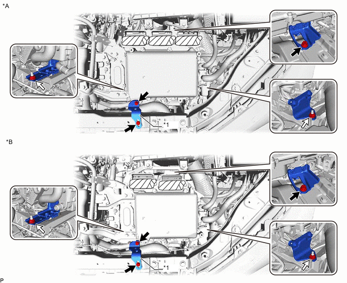
*A for AWD *B for 2WD *1 No. 6 Inverter Bracket - - 
Bolt 
Nut -
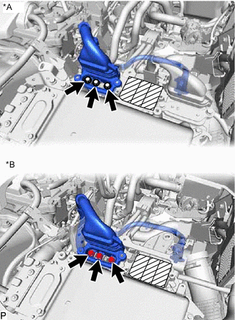
Remove the 2 nuts and bolt and inverter with converter assembly.
Note
-
2 people are needed to remove the inverter with converter assembly from the vehicle.
-
To prevent damage, do not hold the connectors when lifting up the inverter with converter assembly.
-
Cover the hole with non-residue tape to prevent entry of foreign matter or water after removing the connector and grommet.
-
-
Even after the coolant is drained, coolant remains in the inverter with converter assembly due to its internal structure. Therefore, plug or cover the pipes with plastic bags when removing the inverter with converter assembly from the vehicle so that coolant does not spill out or enter the cooling path.
-
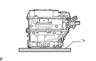
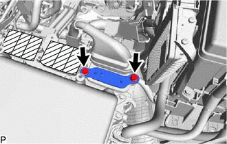
*a Cushion When removing and storing the inverter with converter assembly, make sure to cover the opening with non-residue tape to prevent foreign matter or water from getting inside, and place a cushioning material under the inverter with converter assembly to protect it.
Note
Do not place the inverter with converter assembly upside-down.
-
-
REMOVE HIGH VOLTAGE FUSE
CAUTION:
Be sure to wear insulated gloves.
Tech Tips
Perform this procedure only when replacement of the high voltage fuse is necessary.
-
*A for AWD *B for 2WD Remove the bolt and connector cover assembly.
Note
-
Pull the connector cover assembly straight up, as a connector is connected to the bottom of the cover.
-
Do not allow any foreign objects or water to enter the inverter with converter assembly.
-
-
Remove the 2 nuts and high voltage fuse.
-
Temporarily install the connector cover assembly with the bolt to prevent any foreign objects or water from entering the inverter with converter assembly.
-
-
REMOVE NO. 1 AIR CLEANER BRACKET
-
for AWD:
Remove the bolt and No. 1 air cleaner bracket.
-
for 2WD:
Remove the 2 bolts and No. 1 air cleaner bracket.
-
-
REMOVE AIR CLEANER BRACKET (for AWD)
-
Remove the bolt and air cleaner bracket.
-
-
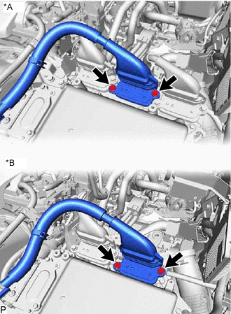
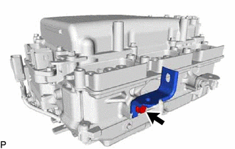
REMOVE NO. 4 INVERTER BRACKET
-
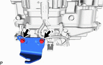
Remove the 2 bolts and No. 4 inverter bracket.
-
-
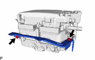
REMOVE NO. 2 INVERTER BRACKET
-
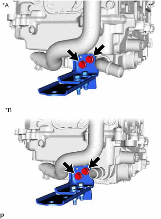
*A for AWD *B for 2WD Remove the 2 bolts and No. 2 inverter bracket.
-
-
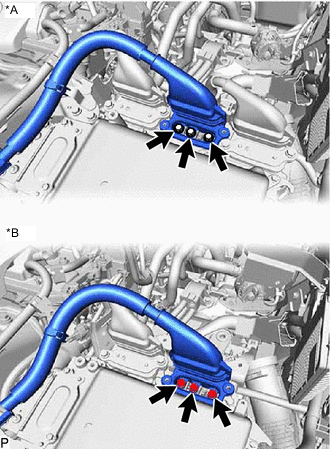
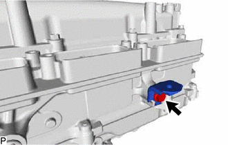
REMOVE NO. 3 INVERTER BRACKET
-
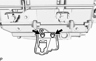
Remove the 2 bolts and No. 3 inverter bracket.
-
-
REMOVE WIRE HARNESS CLAMP BRACKET (for AWD)
-
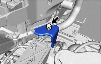
Remove the bolt and wire harness clamp bracket.
-
-
REMOVE HYBRID INVERTER PROTECTOR ASSEMBLY (for AWD)
-
Remove the 2 bolts and hybrid inverter protector assembly.
-
-
REMOVE NO. 2 INVERTER RESERVE TANK BRACKET
-

*A for AWD *B for 2WD Remove the 2 bolts and No. 2 inverter reserve tank bracket.
-
-
REMOVE NO. 3 ENGINE ROOM WIRE
-
Open the terminal cap.
Note
Do not exert unnecessary force when twisting the terminal cap open.
-
Remove the nut and No. 3 engine room wire.
-