HYBRID BATTERY SYSTEM, Diagnostic DTC:P0A7F-123
| DTC Code | DTC Name |
|---|---|
| P0A7F-123 | Hybrid Battery Pack Deterioration |
DESCRIPTION
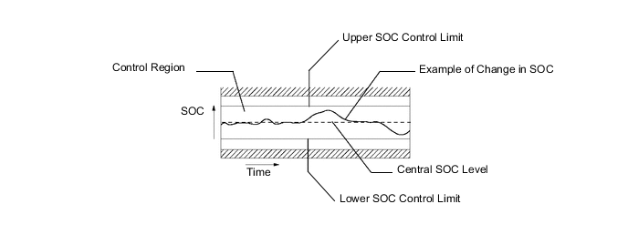
The battery voltage sensor and the hybrid vehicle control ECU calculate the SOC (state of charge) of the HV battery through the accumulated amperage in the HV battery. The battery voltage sensor sends the condition of the HV battery to the hybrid vehicle control ECU. Then the hybrid vehicle control ECU calculates the SOC based on the information and controls HV battery charge and discharge according to the driving condition.
Based on the HV battery voltage and current, the battery voltage sensor calculates the resistance and judges that the HV battery has deteriorated.
| DTC No. | Detection Item | DTC Detection Condition | Trouble Area | MIL | Warning Indicate |
|---|---|---|---|---|---|
| P0A7F-123 | Hybrid Battery Pack Deterioration | Either of the following conditions is met:
|
|
Comes on | Master Warning Light: Comes on |
| DTC No. | Data List |
|---|---|
| P0A7F-123 |
|
The following items can be helpful when performing repairs:
-
Ready Signal
-
Vehicle Spd
-
Accelerator Degree
-
Shift Sensor Shift Pos
-
Engine Revolution
-
Power Resource VB
-
Batt Pack Current Val
-
Auxiliary Battery Vol
-
Battery Low Time
-
DC Inhibit Time
-
SOC after IG-ON
-
Status of Charge Max
-
Status of Charge Min
-
DTC Clear Run Distance
-
Engine Run Time
Data List
-
Main Battery Low Voltage
Operation History Data
Tech Tips
-
This DTC can be stored after clearing DTCs and driving the vehicle for approximately 10 minutes. (As 2 trip detection logic is also used, check for DTCs including pending DTCs.)
-
When the internal resistance of the HV battery increases, battery block voltage may drop.
-
In order to ensure HV battery performance, appropriate cooling performance must be maintained. Perform the following items as necessary. If cooling performance has decreased and "Cooling Performance of The Hybrid Battery Is Low Visit Your Dealer" is displayed on the multi-information display, make sure to perform the following items:
-
Make sure the air intake port is not blocked.
-
Make sure there are no gaps between the connecting parts of the ducts.
-
Clean the filter of the No. 2 or No. 3 hybrid battery intake duct.
-
Clear the DTCs to reset the learning values even if no DTCs are stored.
CAUTION / NOTICE / HINT
CAUTION:
When disposing of an HV battery, make sure to return it through an authorized collection agent who is capable of handling it safely. If the HV battery is returned via the manufacturer specified route, it will be returned properly and in a safe manner by an authorized collection agent.
Tech Tips
After the repair, clear the DTCs, perform the following operations, and check that no DTCs (including pending DTCs) are output.
-
Turn the power switch on (READY) and wait for 30 seconds or more.
Drive the vehicle on urban roads at a speed of 25 mph (40 km/h) or more for a total of at least 10 minutes. (It is not necessary to maintain the vehicle speed at 40 km/h (25 mph) throughout the road test.)
Note
Avoid abrupt acceleration or braking.
This DTC may not be stored if the vehicle is stopped or being driven at a steady speed.
PROCEDURE
-
CHECK DTC OUTPUT (HYBRID CONTROL)
-
Connect the GTS to the DLC3.
-
Turn the power switch on (IG).
-
Enter the following menus: Powertrain / Hybrid Control / Trouble Codes.
-
Check and record any HV system DTCs, INF codes and freeze frame data.
-
Read output DTCs.
Powertrain > Hybrid Control > Trouble CodesResult Result Proceed to P0AFC-123 is not output. A P0AFC-123 is also output. B -
Turn the power switch off.
-
Disconnect the GTS from the DLC3.
B 
GO TO DTC CHART (P0AFC-123) Click here
A 
-
-
READ VALUE USING GTS (VB1 - VB17)
Result Result Proceed to All conditions in table 1 are met. A All conditions in table 2 are met. Other than above B
-
Ensure the safety of the areas in front and at the back of the vehicle.
-
Apply the parking brake and secure the wheels using chocks.
-
Connect the GTS to the DLC3.
-
Turn the power switch on (READY).
-
Fully warm up the engine and turn the air conditioning off.
-
Enter the following menus: Powertrain / Hybrid Control / Data List / Battery Block Vol -V01 to V17.
-
Firmly depress the brake pedal with your left foot.
-
Move the shift lever to D.
-
Record each battery block voltage from the Data List "Battery Block Vol -V01 to V17" while fully depressing the accelerator pedal.
Powertrain > Hybrid Control > Data ListTester Display Battery Block Vol -V01 Battery Block Vol -V02 Battery Block Vol -V03 Battery Block Vol -V04 Battery Block Vol -V05 Battery Block Vol -V06 Battery Block Vol -V07 Battery Block Vol -V08 Battery Block Vol -V09 Battery Block Vol -V10 Battery Block Vol -V11 Battery Block Vol -V12 Battery Block Vol -V13 Battery Block Vol -V14 Battery Block Vol -V15 Battery Block Vol -V16 Battery Block Vol -V17 -
Compare the battery block voltages "Battery Block Vol -V01 to V17" between the even and odd number groups in each combination shown in the tables below.
Table 1 Circuit A Battery Block Circuit B Battery Block Condition Battery Block Vol -V01 (VB1) Battery Block Vol -V02 (VB2) "Battery Block Vol -V01" - "Battery Block Vol -V02" = 0.3 V or more Battery Block Vol -V04 (VB4) Battery Block Vol -V03 (VB3) "Battery Block Vol -V04" - "Battery Block Vol -V03" = 0.3 V or more Battery Block Vol -V05 (VB5) Battery Block Vol -V06 (VB6) "Battery Block Vol -V05" - "Battery Block Vol -V06" = 0.3 V or more Battery Block Vol -V08 (VB8) Battery Block Vol -V07 (VB7) "Battery Block Vol -V08" - "Battery Block Vol -V07" = 0.3 V or more Battery Block Vol -V09 (VB9) Battery Block Vol -V10 (VB10) "Battery Block Vol -V09" - "Battery Block Vol -V10" = 0.3 V or more Battery Block Vol -V12 (VB12) Battery Block Vol -V11 (VB11) "Battery Block Vol -V12" - "Battery Block Vol -V11" = 0.3 V or more Battery Block Vol -V13 (VB13) Battery Block Vol -V14 (VB14) "Battery Block Vol -V13" - "Battery Block Vol -V14" = 0.3 V or more Battery Block Vol -V16 (VB16) Battery Block Vol -V15 (VB15) "Battery Block Vol -V16" - "Battery Block Vol -V15" = 0.3 V or more Battery Block Vol -V17 (VB17) Battery Block Vol -V14 (VB14) "Battery Block Vol -V17" - "Battery Block Vol -V14" = 0.3 V or more Table 2 Circuit A Battery Block Circuit B Battery Block Condition Battery Block Vol -V01 (VB1) Battery Block Vol -V02 (VB2) "Battery Block Vol -V02" - "Battery Block Vol -V01" = 0.3 V or more Battery Block Vol -V04 (VB4) Battery Block Vol -V03 (VB3) "Battery Block Vol -V03" - "Battery Block Vol -V04" = 0.3 V or more Battery Block Vol -V05 (VB5) Battery Block Vol -V06 (VB6) "Battery Block Vol -V06" - "Battery Block Vol -V05" = 0.3 V or more Battery Block Vol -V08 (VB8) Battery Block Vol -V07 (VB7) "Battery Block Vol -V07" - "Battery Block Vol -V08" = 0.3 V or more Battery Block Vol -V09 (VB9) Battery Block Vol -V10 (VB10) "Battery Block Vol -V10" - "Battery Block Vol -V09" = 0.3 V or more Battery Block Vol -V12 (VB12) Battery Block Vol -V11 (VB11) "Battery Block Vol -V11" - "Battery Block Vol -V12" = 0.3 V or more Battery Block Vol -V13 (VB13) Battery Block Vol -V14 (VB14) "Battery Block Vol -V14" - "Battery Block Vol -V13" = 0.3 V or more Battery Block Vol -V16 (VB16) Battery Block Vol -V15 (VB15) "Battery Block Vol -V15" - "Battery Block Vol -V16" = 0.3 V or more Battery Block Vol -V17 (VB17) Battery Block Vol -V14 (VB14) "Battery Block Vol -V14" - "Battery Block Vol -V17" = 0.3 V or more Tech Tips
Make sure to compare Battery Block Vol -V17 to Battery Block Vol -V14 in accordance with the tables above.
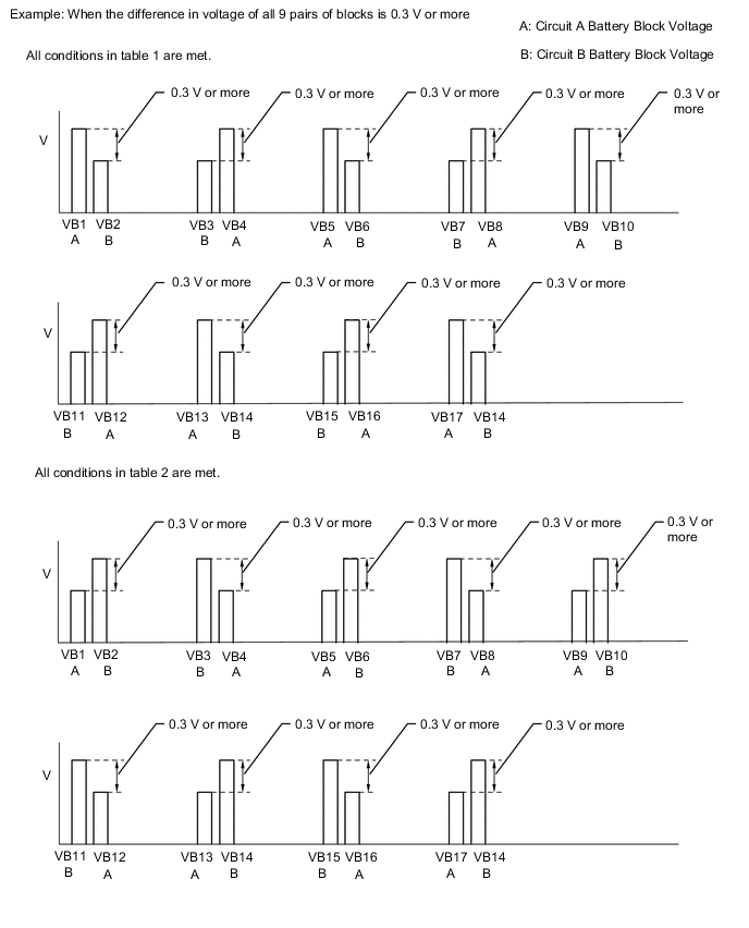
Tech Tips
When an internal malfunction occurs in the battery voltage sensor, this symptom (difference in voltage of 0.3 V or more for all 9 pairs of blocks) will occur.
Result Result Proceed to All conditions in table 1 are met. A All conditions in table 2 are met. Other than above B -
Turn the power switch off.
-
Disconnect the GTS from the DLC3.
A
REPLACE BATTERY VOLTAGE SENSOR Click here
B
REPLACE HV BATTERY Click here
-