HYBRID CONTROL SYSTEM Pattern Select Switch Eco Mode Circuit
DESCRIPTION
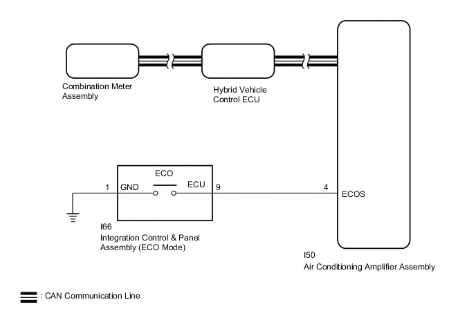
When selecting ECO mode, the mode switch (integration control & panel assembly) operation signal is sent to the air conditioning amplifier assembly. Following this, ECO mode control is activated for the heater and air conditioning system.
WIRING DIAGRAM
PROCEDURE
-
READ VALUE USING GTS (CAN BUS CHECK)
Result Result Proceed to All of the ECUs and sensors that are currently connected to the CAN communication system are displayed. A None of the ECUs and sensors that are currently connected to the CAN communication system are displayed, or some of them are not displayed. B
-
Connect the GTS to the DLC3.
-
Turn the power switch on (IG).
-
Enter the following menus: System Select / CAN Bus Check.
CAN Bus CheckResult Result Proceed to All of the ECUs and sensors that are currently connected to the CAN communication system are displayed. A None of the ECUs and sensors that are currently connected to the CAN communication system are displayed, or some of them are not displayed. B -
Turn the power switch off.
B 
GO TO CAN COMMUNICATION SYSTEM Click here
A 
-
-
CHECK DTC OUTPUT (HEALTH CHECK)
Result Proceed to No DTCs are output. DTCs are output.
-
Connect the GTS to the DLC3.
-
Turn the power switch on (IG).
-
Enter the following menus: System Select / Health Check.
-
Check for DTCs.
Result Result Proceed to No DTCs are output. A DTCs are output. B -
Turn the power switch off.
DTCs are output.
GO TO DTC CHART
No DTCs are output.
-
-
READ VALUE USING GTS (ECO MODE)
-
Connect the GTS to the DLC3.
-
Turn the power switch on (IG).
-
Enter the following menus: Powertrain / Hybrid Control / Data List / ECO Mode.
Powertrain > Hybrid Control > Data ListTester Display ECO Mode -
Read the value displayed on the GTS.
Powertrain > Hybrid Control > Data ListTester Display Measurement Item Range Normal Condition ECO Mode ECO mode transition availability ON or OFF In ECO mode: ON Result Result Proceed to The GTS display changes according to the integration control & panel assembly operation. A The GTS display does not change according to the integration control & panel assembly operation. B
A
CHECK FOR INTERMITTENT PROBLEMS Click here
B
-
-
READ VALUE USING GTS (ECO SWITCH)
-
Connect the GTS to the DLC3.
-
Turn the power switch on (IG).
-
Enter the following menus: Body Electrical / Air Conditioning / Data List / ECO Switch.
Body Electrical > Air Conditioner > Data ListTester Display ECO Switch -
Read the value displayed on the GTS.
Body Electrical > Air Conditioner > Data ListTester Display Measurement Item Range Normal Condition ECO Switch Integration control & panel assembly condition ON or OFF Integration control & panel assembly being turned and held at ECO position: ON
Integration control & panel assembly not turned: OFF
Result Result Proceed to The GTS display changes according to the integration control & panel assembly operation. A The GTS display does not change according to the integration control & panel assembly operation. B
A
REPLACE AIR CONDITIONING AMPLIFIER ASSEMBLY Click here
B
-
-
INSPECT INTEGRATION CONTROL & PANEL ASSEMBLY
-
Remove the integration control & panel assembly.
-
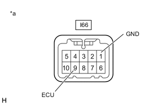
*a Component without harness connected
(Integration Control & Panel Assembly)
Measure the resistance according to the value(s) in the table below.
Standard Resistance Tester Connection Condition Specified Condition I66-9 (ECU) - I66-1 (GND) Integration control & panel assembly being turned and held at ECO position Below 10 Ω Integration control & panel assembly not turned 10 kΩ or higher -
Install the integration control & panel assembly.
Result Proceed to OK NG
NG
REPLACE INTEGRATION CONTROL & PANEL ASSEMBLY Click here
OK
-
-
CHECK HARNESS AND CONNECTOR (INTEGRATION CONTROL & PANEL ASSEMBLY - BODY GROUND)
Result Proceed to OK NG
-
Disconnect the I66 integration control & panel assembly connector.
-
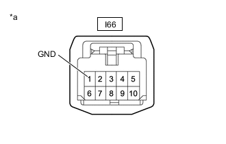
*a Front view of wire harness connector
(to Integration Control & Panel Assembly)
Measure the resistance according to the value(s) in the table below.
Standard Resistance Tester Connection Condition Specified Condition I66-1 (GND) - Body ground Always Below 1 Ω -
Reconnect the I66 integration control & panel assembly connector.
Result Proceed to OK NG
NG
REPAIR OR REPLACE HARNESS OR CONNECTOR
OK
-
-
CHECK HARNESS AND CONNECTOR (AIR CONDITIONING AMPLIFIER ASSEMBLY - INTEGRATION CONTROL & PANEL ASSEMBLY)
-
Disconnect the I50 air conditioning amplifier assembly connector.
-
Disconnect the I66 integration control & panel assembly connector.
-
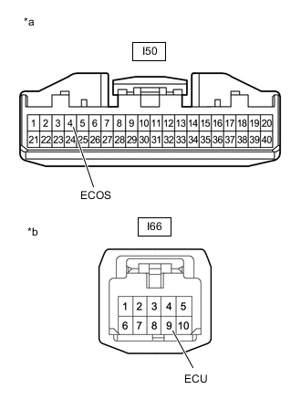
*a Front view of wire harness connector
(to Air Conditioning Amplifier Assembly)
*b Front view of wire harness connector
(to Integration Control & Panel Assembly)
Measure the resistance according to the value(s) in the table below.
Standard Resistance Tester Connection Condition Specified Condition I50-4 (ECOS) - I66-9 (ECU) Always Below 1 Ω I50-4 (ECOS) or I66-9 (ECU) - Body ground Always 10 kΩ or higher -
Reconnect the I66 integration control & panel assembly connector.
-
Reconnect the I50 air conditioning amplifier assembly connector.
Result Proceed to OK NG
OK
REPLACE AIR CONDITIONING AMPLIFIER ASSEMBLY Click here
NG
REPAIR OR REPLACE HARNESS OR CONNECTOR
-