HYBRID CONTROL SYSTEM, Diagnostic DTC:P0A79-716
| DTC Code | DTC Name |
|---|---|
| P0A79-716 | Drive Motor "B" Inverter Performance |
DTC SUMMARY
-
MALFUNCTION DESCRIPTION
-
Inverter with converter assembly internal circuit malfunction
Internal inverter malfunction
-
Open or short circuit
-
Damage from iron particles or other foreign objects
Rear traction motor with transaxle assembly malfunction
-
DESCRIPTION
For a description of the inverter.
Tech Tips
The term "drive motor B" indicates the rear motor (MGR).
| DTC No. | Detection Item | DTC Detection Condition | Trouble Area | MIL | Warning Indicate |
|---|---|---|---|---|---|
| P0A79-716 | Drive Motor "B" Inverter Performance | Malfunction (short circuit) in the rear motor inverter inside the inverter with converter assembly: Current flowing to any of the phases exceeds a certain level after a DTC (indicating a rear motor inverter malfunction: overheating, overcurrent or circuit malfunction) is stored and the rear motor inverter is shutdown (1 trip detection logic) |
|
Comes on | Master Warning Light: Comes on |
CAUTION / NOTICE / HINT
CAUTION:
-
Before inspecting the high-voltage system or disconnecting the low voltage connector of the inverter with converter assembly, take safety precautions such as wearing insulated gloves and removing the service plug grip to prevent electrical shocks. After removing the service plug grip, put it in your pocket to prevent other technicians from accidentally reconnecting it while you are working on the high-voltage system.
-
After removing the service plug grip, wait for at least 10 minutes before touching any of the high-voltage connectors or terminals. After waiting for 10 minutes, check the voltage at the terminals in the inspection point in the inverter with converter assembly. The voltage should be 0 V before beginning work.
Tech Tips
Waiting for at least 10 minutes is required to discharge the high-voltage capacitor inside the inverter with converter assembly.
Note
-
After turning the power switch off, waiting time may be required before disconnecting the cable from the negative (-) auxiliary battery terminal. Therefore, make sure to read the disconnecting the cable from the negative (-) auxiliary battery terminal notices before proceeding with work.
-
DTC P0A79-716 is stored after DTC P0A1C-693, P0A46-695, P0A79-692, 694, 696 and/or 712 is stored. After troubleshooting and repairing the malfunction which caused DTC P0A79-716 to be stored, be sure to troubleshoot all the other DTCs.
-
Depending on the conditions in which the vehicle is being operated when a short circuit occurs in the inverter with converter assembly, the No. 2 frame wire (rear motor cable), extension wire assembly, or rear traction motor with transaxle assembly may be affected. As this DTC is stored if a short circuit occurs in the inverter with converter assembly, perform a road test to check the No. 2 frame wire (rear motor cable), extension wire assembly, and rear traction motor with transaxle assembly. If problems are found, replace the malfunctioning parts.
-
After completing the repair, including the repair of malfunctions which caused previously output DTCs, drive the vehicle at a speed of approximately 40 km/h (25 mph) for 1 minute and check that DTC P0A91-705 (Drive Motor "B" Performance) is not output. If DTC P0A91-705 (Drive Motor "B" Performance) is output, replace the rear traction motor with transaxle assembly.
Tech Tips
After the repair, clear the DTCs and perform the following procedure to check that DTCs are not output.
-
With the engine stopped, the power switch on (READY) and shift lever in P, depress the accelerator pedal to start the engine.
-
Perform a road test according to the freeze frame data item "Vehicle Spd" for approximately 10 minutes.
PROCEDURE
-
CHECK REAR TRACTION MOTOR WITH TRANSAXLE ASSEMBLY (REAR MOTOR (MGR))
Result Proceed to OK NG CAUTION:
Be sure to wear insulated gloves.
-
Check that the service plug grip is not installed.
Note
After removing the service plug grip, do not turn the power switch on (READY), unless instructed by the repair manual because this may cause a malfunction.
-
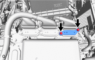
Remove the inverter cover UPR from the inverter with converter assembly.
-
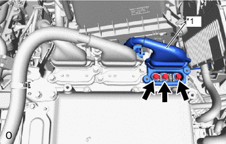
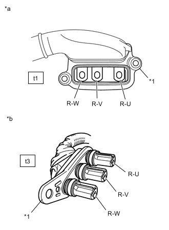
*1 No. 2 Frame Wire (Rear Motor Cable) Disconnect the No. 2 frame wire (rear motor cable) from the inverter with converter assembly.
-
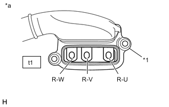
*1 Shield Ground *a No. 2 Frame Wire (rear motor cable)
(Inverter with Converter Assembly Side)
Check the rear motor (MGR) for an interphase short using a milliohmmeter.
-
Using a milliohmmeter, measure the resistance according to the value(s) in the table below.
Tech Tips
If the rear motor (MGR) temperature is high, the resistance will vary greatly from the specification. Therefore, measure the resistance at least 8 hours after the vehicle is stopped.
Standard Resistance Tester Connection Condition Specified Condition t1-1 (R-W) - t1-3 (R-U) Power switch off 163 to 176 mΩ t1-2 (R-V) - t1-1 (R-W) Power switch off 163 to 176 mΩ t1-3 (R-U) - t1-2 (R-V) Power switch off 163 to 176 mΩ Tech Tips
To correct the variation of the measured resistance due to temperature, use the following formula to calculate the resistance at 20°C (68°F).
R20 = Rt / {1 + 0.00393 X (T - 20)}
The calculation is based on the following:
R20: Resistance at 20°C (68°F) (mΩ)
Rt: Measured resistance (mΩ)
T: Temperature when the resistance is measured (°C (°F).)
-
-
When checking for a short circuit between rear motor phases without using a milliohmmeter.
Note
The rear motor generates current when wheels are rotated by hand. Before performing the inspection, wrap the rear motor cable terminals with tape (non-residue type) or equivalent.
Tech Tips
A short circuit between the rear motor phases can be checked simply without using a milliohmmeter.
-
Connect the cable to the negative (-) auxiliary battery terminal.
-
Turn the power switch on (IG).
Note
Turning the power switch on (IG) with the service plug grip removed causes other DTCs to be stored. Clear the DTCs after performing this inspection.
-
Move the shift lever to N.
-
Lift up the vehicle.
-
Rotate the rear wheels in the same direction simultaneously by hand.
Standard Left and right wheels rotate smoothly (No short circuit between phases) Tech Tips
If a short circuit exists between the rear motor phases, the rear wheels do not rotate smoothly (some resistance is felt).
-
Lower the vehicle.
-
Move the shift lever to P.
-
Turn the power switch off.
-
Disconnect the cable from the negative (-) auxiliary battery terminal.
-
-
Using a megohmmeter set to 500 V, measure the resistance according to the value(s) in the table below.
Note
Be sure to set the megohmmeter to 500 V when performing this test. Using a setting higher than 500 V can result in damage to the component being inspected.
Standard Resistance Tester Connection Condition Specified Condition t1-1 (R-W) - Body ground and shield ground Power switch off 100 MΩ or higher t1-2 (R-V) - Body ground and shield ground Power switch off 100 MΩ or higher t1-3 (R-U) - Body ground and shield ground Power switch off 100 MΩ or higher -
Measure the resistance according to the value(s) in the table below.
Tech Tips
Perform this procedure only when checking for a short circuit between rear motor phases without using a milliohmmeter.
Standard Resistance Tester Connection Condition Specified Condition t1-1 (R-W) - t1-2 (R-V) Power switch off Below 1 Ω t1-2 (R-V) - t1-3 (R-U) Power switch off Below 1 Ω -
Reconnect the No. 2 frame wire (rear motor cable).
-
Install the inverter cover UPR.
Result Proceed to OK NG
OK 
GO TO STEP 14 Click here
NG 
-
-
CHECK NO. 2 FRAME WIRE (REAR MOTOR CABLE)
Result Proceed to OK NG CAUTION:
Be sure to wear insulated gloves.
-
Check that the service plug grip is not installed.
Note
After removing the service plug grip, do not turn the power switch on (READY), unless instructed by the repair manual because this may cause a malfunction.
-
Remove the inverter cover UPR from the inverter with converter assembly.
-
*1 No. 2 Frame Wire (Rear Motor Cable) Disconnect the No. 2 frame wire (rear motor cable) from the inverter with converter assembly.
-
Disconnect the No. 2 frame wire (rear motor cable) from the rear traction motor with transaxle assembly.
-
*1 Shield Ground *a No. 2 Frame Wire (rear motor cable)
(Inverter with Converter Assembly Side)
Using a megohmmeter set to 500 V, measure the resistance according to the value(s) in the table below.
Note
Be sure to set the megohmmeter to 500 V when performing this test. Using a setting higher than 500 V can result in damage to the component being inspected.
Standard Resistance Tester Connection Condition Specified Condition t1-1 (R-W) - Body ground and shield ground Power switch off 10 MΩ or higher t1-2 (R-V) - Body ground and shield ground Power switch off 10 MΩ or higher t1-3 (R-U) - Body ground and shield ground Power switch off 10 MΩ or higher Note
Wrap the terminals of three-phase AC cable with insulating tape to avoid them coming into contact with body ground.
-
*1 Shield Ground *a No. 2 Frame Wire (rear motor cable)
(Inverter with Converter Assembly Side)
*b No. 2 Frame Wire (rear motor cable)
(Rear Traction Motor with Transaxle Assembly Side)
Measure the resistance according to the value(s) in the table below.
Standard Resistance Tester Connection Condition Specified Condition t1-1 (R-W) - t3-1 (R-W) Power switch off Below 1 Ω t1-2 (R-V) - t3-2 (R-V) Power switch off Below 1 Ω t1-3 (R-U) - t3-3 (R-U) Power switch off Below 1 Ω t1-1 (R-W) - t3-3 (R-U) Power switch off 10 kΩ or higher t1-2 (R-V) - t3-1 (R-W) Power switch off 10 kΩ or higher t1-3 (R-U) - t3-2 (R-V) Power switch off 10 kΩ or higher -
Connect the No. 2 frame wire (rear motor cable) to the rear traction motor with transaxle assembly.
-
Connect the No. 2 frame wire (rear motor cable) to the inverter with converter assembly.
-
Install the inverter cover UPR.
Result Proceed to OK NG
NG
CHECK EXTENSION WIRE ASSEMBLY Click here
OK
-
-
CHECK EXTENSION WIRE ASSEMBLY
Result Proceed to OK NG CAUTION:
Be sure to wear insulated gloves.
-
Check that the service plug grip is not installed.
Note
After removing the service plug grip, do not turn the power switch on (READY), unless instructed by the repair manual because this may cause a malfunction.
-
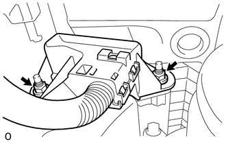
Remove the extension wire assembly from the rear traction motor with transaxle assembly.
-
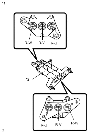
*1 Extension Wire Assembly *2 Shield Shell Using a megohmmeter set to 500 V, measure the resistance according to the value(s) in the table below.
Note
Be sure to set the megohmmeter to 500 V when performing this test. Using a setting higher than 500 V can result in damage to the component being inspected.
Standard Resistance Tester Connection Condition Specified Condition R-U - Shield shell Power switch off 100 MΩ or higher R-V - Shield shell Power switch off 100 MΩ or higher R-W - Shield shell Power switch off 100 MΩ or higher -
Measure the resistance according to the value(s) in the table below.
Standard Resistance Tester Connection Condition Specified Condition R-U - R-U Power switch off Below 1 Ω R-V - R-V Power switch off Below 1 Ω R-W - R-W Power switch off Below 1 Ω R-U - R-V Power switch off 100 kΩ or higher R-V - R-W Power switch off 100 kΩ or higher R-W - R-U Power switch off 100 kΩ or higher -
Install the extension wire.
Result Proceed to OK NG
NG
CHECK REAR TRACTION MOTOR WITH TRANSAXLE ASSEMBLY (REAR MOTOR (MGR)) Click here
OK
-
-
REPLACE REAR TRACTION MOTOR WITH TRANSAXLE ASSEMBLY
Result Proceed to NEXT
NEXT
GO TO STEP 14 Click here
-
CHECK EXTENSION WIRE ASSEMBLY
Result Proceed to OK NG CAUTION:
Be sure to wear insulated gloves.
-
Check that the service plug grip is not installed.
Note
After removing the service plug grip, do not turn the power switch on (READY), unless instructed by the repair manual because this may cause a malfunction.
-
Remove the extension wire assembly from the rear traction motor with transaxle assembly.
-
*1 Extension Wire Assembly *2 Shield Shell Using a megohmmeter set to 500 V, measure the resistance according to the value(s) in the table below.
Note
Be sure to set the megohmmeter to 500 V when performing this test. Using a setting higher than 500 V can result in damage to the component being inspected.
Standard Resistance Tester Connection Condition Specified Condition R-U - Shield shell Power switch off 100 MΩ or higher R-V - Shield shell Power switch off 100 MΩ or higher R-W - Shield shell Power switch off 100 MΩ or higher -
Measure the resistance according to the value(s) in the table below.
Standard Resistance Tester Connection Condition Specified Condition R-U - R-U Power switch off Below 1 Ω R-V - R-V Power switch off Below 1 Ω R-W - R-W Power switch off Below 1 Ω R-U - R-V Power switch off 100 kΩ or higher R-V - R-W Power switch off 100 kΩ or higher R-W - R-U Power switch off 100 kΩ or higher -
Install the extension wire.
Result Proceed to OK NG
NG
CHECK REAR TRACTION MOTOR WITH TRANSAXLE ASSEMBLY (REAR MOTOR (MGR)) Click here
OK
-
-
CHECK REAR TRACTION MOTOR WITH TRANSAXLE ASSEMBLY (REAR MOTOR (MGR))
CAUTION:
Be sure to wear insulated gloves.
-
Check that the service plug grip is not installed.
Note
After removing the service plug grip, do not turn the power switch on (READY), unless instructed by the repair manual because this may cause a malfunction.
-
Remove the No. 2 frame wire (rear motor cable) and extension wire assembly from the rear traction motor with transaxle assembly.
-
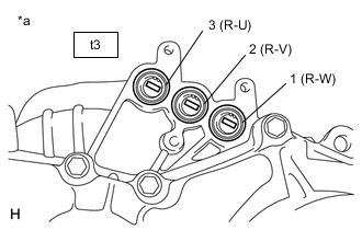
*a Component without rear motor cable connected
(Rear Traction Motor with Transaxle Assembly)
Check the rear motor (MGR) for an interphase short using a milliohmmeter.
-
Using a milliohmmeter, measure the resistance according to the value(s) in the table below.
Tech Tips
If the rear motor (MGR) temperature is high, the resistance will vary greatly from the specification. Therefore, measure the resistance at least 8 hours after the vehicle is stopped.
Standard Resistance Tester Connection Condition Specified Condition t3-3 (R-U) - t3-2 (R-V) Power switch off 143 to 155 mΩ t3-2 (R-V) - t3-1 (R-W) Power switch off 143 to 155 mΩ t3-1 (R-W) - t3-3 (R-U) Power switch off 143 to 155 mΩ Tech Tips
To correct the variation of the measured resistance due to temperature, use the following formula to calculate the resistance at 20°C (68°F).
R20 = Rt / {1 + 0.00393 X (T - 20)}
The calculation is based on the following:
R20: Resistance at 20°C (68°F) (mΩ)
Rt: Measured resistance (mΩ)
T: Temperature when the resistance is measured (°C (°F).)
-
-
When checking for a short circuit between rear motor phases without using a milliohmmeter.
Note
The rear motor generates current when wheels are rotated by hand. Before performing the inspection, wrap the rear motor cable terminals with tape (non-residue type) or equivalent.
Tech Tips
A short circuit between the rear motor phases can be checked simply without using a milliohmmeter.
-
Connect the cable to the negative (-) auxiliary battery terminal.
-
Turn the power switch on (IG).
Note
Turning the power switch on (IG) with the service plug grip removed causes other DTCs to be stored. Clear the DTCs after performing this inspection.
-
Move the shift lever to N.
-
Lift up the vehicle.
-
Rotate the rear wheels in the same direction simultaneously by hand.
Standard Reae wheels rotate smoothly (No short circuit between phases) Tech Tips
If a short circuit exists between the rear motor phases, the rear wheels do not rotate smoothly (some resistance is felt).
-
Lower the vehicle.
-
Move the shift lever to P.
-
Turn the power switch off.
-
Disconnect the cable from the negative (-) auxiliary battery terminal.
-
-
Using a megohmmeter set to 500 V, measure the resistance according to the value(s) in the table below.
Note
Be sure to set the megohmmeter to 500 V when performing this test. Using a setting higher than 500 V can result in damage to the component being inspected.
Standard Resistance Tester Connection Condition Specified Condition t3-3 (R-U) - Body ground Power switch off 100 MΩ or higher t3-2 (R-V) - Body ground Power switch off 100 MΩ or higher t3-1 (R-W) - Body ground Power switch off 100 MΩ or higher -
Measure the resistance according to the value(s) in the table below.
Tech Tips
Perform this procedure only when checking for a short circuit between rear motor phases without using a milliohmmeter.
Standard Resistance Tester Connection Condition Specified Condition t3-1 (R-W) - t3-2 (R-V) Power switch off Below 1 Ω t3-2 (R-V) - t3-3 (R-U) Power switch off Below 1 Ω -
Install the No. 2 frame wire (rear motor cable) and extension wire assembly to the rear traction motor with transaxle assembly.
Result Proceed to OK NG
NG
REPLACE REAR TRACTION MOTOR WITH TRANSAXLE ASSEMBLY Click here
OK
-
-
REPLACE NO. 2 FRAME WIRE
Result Proceed to NEXT
NEXT
GO TO STEP 14 Click here
-
CHECK REAR TRACTION MOTOR WITH TRANSAXLE ASSEMBLY (REAR MOTOR (MGR))
CAUTION:
Be sure to wear insulated gloves.
-
Check that the service plug grip is not installed.
Note
After removing the service plug grip, do not turn the power switch on (READY), unless instructed by the repair manual because this may cause a malfunction.
-
Remove the No. 2 frame wire (rear motor cable) and extension wire assembly from the rear traction motor with transaxle assembly.
-
*a Component without rear motor cable connected
(Rear Traction Motor with Transaxle Assembly)
Check the rear motor (MGR) for an interphase short using a milliohmmeter.
-
Using a milliohmmeter, measure the resistance according to the value(s) in the table below.
Tech Tips
If the rear motor (MGR) temperature is high, the resistance will vary greatly from the specification. Therefore, measure the resistance at least 8 hours after the vehicle is stopped.
Standard Resistance Tester Connection Condition Specified Condition t3-3 (R-U) - t3-2 (R-V) Power switch off 142 to 155 mΩ t3-2 (R-V) - t3-1 (R-W) Power switch off 142 to 155 mΩ t3-1 (R-W) - t3-3 (R-U) Power switch off 142 to 155 mΩ Tech Tips
To correct the variation of the measured resistance due to temperature, use the following formula to calculate the resistance at 20°C (68°F).
-
R20 = Rt / {1 + 0.00393 X (T - 20)}
The calculation is based on the following:
-
R20: Resistance at 20°C (68°F) (mΩ)
-
Rt: Measured resistance (mΩ)
-
T: Temperature when the resistance is measured (°C (°F))
-
-
-
Using a megohmmeter set to 500 V, measure the resistance according to the value(s) in the table below.
Note
Be sure to set the megohmmeter to 500 V when performing this test. Using a setting higher than 500 V can result in damage to the component being inspected.
Standard Resistance Tester Connection Condition Specified Condition t3-3 (R-U) - Body ground Power switch off 100 MΩ or higher t3-2 (R-V) - Body ground Power switch off 100 MΩ or higher t3-1 (R-W) - Body ground Power switch off 100 MΩ or higher -
Install the No. 2 frame wire (rear motor cable) and extension wire assembly to the rear traction motor with transaxle assembly.
Result Proceed to OK NG
NG
REPLACE REAR TRACTION MOTOR WITH TRANSAXLE ASSEMBLY Click here
OK
-
-
REPLACE EXTENSION WIRE ASSEMBLY
Result Proceed to NEXT
NEXT
GO TO STEP 13 Click here
-
REPLACE REAR TRACTION MOTOR WITH TRANSAXLE ASSEMBLY
Result Proceed to NEXT
NEXT
-
REPLACE NO. 2 FRAME WIRE
Result Proceed to NEXT
NEXT
-
REPLACE INVERTER WITH CONVERTER ASSEMBLY
Result Proceed to NEXT
NEXT
-
CHECK DTC OUTPUT
-
Check the other DTCs that were output together with DTC P0A79-716.
Result DTC No. Relevant Diagnosis P0A1C-693 Drive Motor "B" Control Module P0A46-695 Drive Motor "B" Position Sensor Circuit Range / Performance P0A79-692, 694, 696, 712 Drive Motor "B" Inverter Performance Note
DTC P0A79-716 is stored after DTC P0A1C-693, P0A46-695, P0A79-692, 694, 696 and/or 712 is stored. After troubleshooting and repairing the malfunction which caused DTC P0A79-716 to be stored, be sure to troubleshoot all the other DTCs.
Result Proceed to NEXT
NEXT 
GO TO DTC CHART (HYBRID CONTROL SYSTEM) Click here
-
-
REPLACE REAR TRACTION MOTOR WITH TRANSAXLE ASSEMBLY
Result Proceed to NEXT
NEXT
-
REPLACE EXTENSION WIRE ASSEMBLY
Result Proceed to NEXT
NEXT
GO TO STEP 14 Click here
-
REPLACE REAR TRACTION MOTOR WITH TRANSAXLE ASSEMBLY
Result Proceed to NEXT
NEXT
-
REPLACE EXTENSION WIRE ASSEMBLY
Result Proceed to NEXT
NEXT
GO TO STEP 13 Click here