HYBRID CONTROL SYSTEM, Diagnostic DTC:P0A51-174
| DTC Code | DTC Name |
|---|---|
| P0A51-174 | Drive Motor "A" Current Sensor Circuit |
DESCRIPTION
The MG ECU, which is built into the inverter with converter assembly, monitors its internal operation and will store DTCs when the system is malfunctioning.
Tech Tips
The term "drive motor A" indicates the motor (MG2).
| DTC No. | Detection Item | DTC Detection Condition | Trouble Area | MIL | Warning Indicate |
|---|---|---|---|---|---|
| P0A51-174 | Drive Motor "A" Current Sensor Circuit | Motor current sensor high resolution circuit signal is out of range or there is a difference between it and the motor current sensor low resolution circuit current value. (1 trip detection logic) |
|
Does not come on | Master Warning Light: Comes on |
CAUTION / NOTICE / HINT
CAUTION:
-
Before inspecting the high-voltage system or disconnecting the low voltage connector of the inverter with converter assembly, take safety precautions such as wearing insulated gloves and removing the service plug grip to prevent electrical shocks. After removing the service plug grip, put it in your pocket to prevent other technicians from accidentally reconnecting it while you are working on the high-voltage system.
-
After removing the service plug grip, wait for at least 10 minutes before touching any of the high-voltage connectors or terminals. After waiting for 10 minutes, check the voltage at the terminals in the inspection point in the inverter with converter assembly. The voltage should be 0 V before beginning work.
Tech Tips
Waiting for at least 10 minutes is required to discharge the high-voltage capacitor inside the inverter with converter assembly.
Note
After turning the power switch off, waiting time may be required before disconnecting the cable from the negative (-) auxiliary battery terminal. Therefore, make sure to read the disconnecting the cable from the negative (-) auxiliary battery terminal notices before proceeding with work.
Tech Tips
After the repair, clear the DTCs and perform the following procedure to check that DTCs are not output.
-
Turn the power switch on (IG) and wait for 5 seconds or more.
PROCEDURE
-
CHECK DTC OUTPUT (HYBRID CONTROL)
-
Connect the GTS to the DLC3.
-
Turn the power switch on (IG).
-
Enter the following menus: Powertrain / Hybrid Control / Trouble Codes.
-
Check for DTCs.
Powertrain > Hybrid Control > Trouble CodesResult Result Proceed to P0A51-174 only is output, or DTCs except the ones in the table below are also output. A Any of the following DTCs are also output. B Relevant DTC P0BEA-290 Drive Motor "A" Phase V Current Sensor Circuit Range / Performance P1C3C-294 Drive Motor "A" Phase V Current Sensor Correlation P1C4A-288 Drive Motor "A" Phase V Current Sensor Sub Circuit Range / Performance P1C6D-501 Drive Motor "A" Phase V Current Sensor Offset Range / Performance P0BEE-298 Drive Motor "A" Phase W Current Sensor Circuit Range / Performance P1C3D-302 Drive Motor "A" Phase W Current Sensor Correlation P1C4F-296 Drive Motor "A" Phase W Current Sensor Sub Circuit Range / Performance P1C6E-502 Drive Motor "A" Phase W Current Sensor Offset Range / Performance P0A1B-505 Drive Motor "A" Control Module P0A40-506 Drive Motor "A" Position Sensor Circuit Range / Performance P0A78-113, 287 Drive Motor "A" Inverter Performance Tech Tips
-
*1: If any INF codes are output for this DTC, refer to the corresponding diagnostic procedure.
-
P0A51-174 may be stored due to a malfunction which causes the DTCs in the preceding table to be stored. In this case, first troubleshoot the output DTCs in the preceding table. Then, perform a reproduction test to check that no DTCs are output.
-
-
Turn the power switch off.
B 
GO TO DTC CHART (HYBRID CONTROL SYSTEM) Click here
A 
-
-
CHECK CONNECTOR CONNECTION CONDITION (INVERTER WITH CONVERTER ASSEMBLY CONNECTOR)
Result Result Proceed to OK A NG (The connector is not connected securely.) B NG (The terminals are not making secure contact or are deformed, or water or foreign matter exists in the connector.) C CAUTION:
Be sure to wear insulated gloves.
-
Check that the service plug grip is not installed.
Note
After removing the service plug grip, do not turn the power switch on (READY), unless instructed by the repair manual because this may cause a malfunction.
-
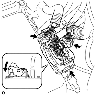
Check the connection condition of the low voltage connector of the inverter with converter assembly and the contact pressure of each terminal. Check the terminals for deformation, and check the connector for water ingress and foreign matter.
Note
Before disconnecting the connector, confirm that it is properly connected by checking that the locking claws are engaged and that the connector does not pull out.
OK - The connector is connected securely. - The terminals are not deformed and are connected securely. - No water or foreign matter in the connector. Result Result Proceed to OK A NG (The connector is not connected securely.) B NG (The terminals are not making secure contact or are deformed, or water or foreign matter exists in the connector.) C Tech Tips
When connecting the connector, insert it with the locking lever in the raised position. Rotate the lever downward and make sure that the connector is pulled into its socket. When the locking lever is in its fully closed position, a click will be heard as its locking claws engage. After the click is heard, pull up on the connector to confirm that it is properly connected.
A
REPLACE INVERTER WITH CONVERTER ASSEMBLY Click here
B
CONNECT SECURELY
C
REPAIR OR REPLACE HARNESS OR CONNECTOR
-