SFI SYSTEM(w/ Canister Pump Module), Diagnostic DTC:P0560
| DTC Code | DTC Name |
|---|---|
| P0560 | System Voltage |
MONITOR DESCRIPTION
The auxiliary battery supplies electricity to the ECM even when the power switch is off. This power allows the ECM to store data such as DTC history, freeze frame data and fuel trim values. If the auxiliary battery voltage falls below a minimum level, the memory is cleared and the ECM determines that there is a malfunction in the power supply circuit. The ECM will illuminate the MIL and store this DTC.
| DTC No. | Detection Item | DTC Detection Condition | Trouble Area | MIL | Memory |
|---|---|---|---|---|---|
| P0560 | System Voltage | An open in the ECM back up power source circuit (1 trip detection logic). |
|
Comes on | DTC stored |
Tech Tips
If DTC P0560 is stored, the ECM does not store other DTCs or the data stored in the ECM is partially cleared.
MONITOR STRATEGY
| Required Sensors/Components | ECM |
| Frequency of Operation | Continuous |
TYPICAL MALFUNCTION THRESHOLDS
| Stand-by RAM | Initialized |
| Continuous auxiliary battery voltage | Less than 3.5 V |
CONFIRMATION DRIVING PATTERN
-
Turn the power switch on (IG) and wait for 5 seconds or more.
WIRING DIAGRAM
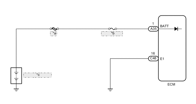
| *a | MAIN |
| *b | EFI-MAIN NO.1 |
| *c | Auxiliary Battery |
CAUTION / NOTICE / HINT
Note
-
Inspect the fuses for circuits related to this system before performing the following procedure.
-
After turning power switch off, waiting time may be required before disconnecting the cable from the negative (-) auxiliary battery terminal. Therefore, make sure to read the disconnecting the cable from the negative (-) auxiliary battery terminal notices before proceeding with work.
Tech Tips
Read freeze frame data using the GTS. The ECM records vehicle and driving condition information as freeze frame data the moment a DTC is stored. When troubleshooting, freeze frame data can help determine if the vehicle was moving or stationary, if the engine was warmed up or not, if the air fuel ratio was lean or rich, and other data from the time the malfunction occurred.
PROCEDURE
-
INSPECT AUXILIARY BATTERY
-
Inspect the auxiliary battery.
OK Auxiliary battery is not depleted Result Proceed to OK NG
NG 
CHARGE OR REPLACE AUXILIARY BATTERY
OK 
-
-
CHECK AUXILIARY BATTERY TERMINAL
-
Check that the auxiliary battery terminals are not loose or corroded.
OK Auxiliary battery terminals are not loose or corroded. Result Proceed to OK NG
NG
REPAIR OR REPLACE AUXILIARY BATTERY TERMINAL
OK
-
-
CHECK TERMINAL VOLTAGE (POWER SOURCE OF ECM)
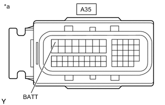
*a Front view of wire harness connector
(to ECM)
-
Disconnect the ECM connector.
-
Measure the voltage according to the value(s) in the table below.
Standard Voltage Tester Connection Condition Specified Condition A35-1 (BATT) - Body ground Always 11 to 16 V Result Proceed to OK NG
NG
REPAIR OR REPLACE HARNESS OR CONNECTOR (AUXILIARY BATTERY - ECM)
OK
-
-
CHECK WHETHER DTC OUTPUT RECURS (DTC P0560)
-
Connect the GTS to the DLC3.
-
Turn the power switch on (IG).
-
Turn the GTS on.
-
Clear the DTCs.
Powertrain > Engine and ECT > Clear DTCs -
Turn the power switch off and wait for at least 30 seconds.
-
Turn the power switch on (IG) and turn the GTS on.
-
Wait 5 seconds or more.
-
Enter the following menus: Powertrain / Engine and ECT / Trouble Codes.
-
Read the DTCs.
Powertrain > Engine and ECT > Trouble CodesResult Result Proceed to DTC P0560 is output A DTCs are not output B
A
REPLACE ECM Click here
B
CHECK FOR INTERMITTENT PROBLEMS Click here
-