SFI SYSTEM(w/ Canister Pump Module), Diagnostic DTC:P014C, P014D, P015A, P015B
| DTC Code | DTC Name |
|---|---|
| P014C | A/F Sensor Slow Response - Rich to Lean Bank 1 Sensor 1 |
| P014D | A/F Sensor Slow Response - Lean to Rich Bank 1 Sensor 1 |
| P015A | A/F Sensor Delayed Response - Rich to Lean Bank 1 Sensor 1 |
| P015B | A/F Sensor Delayed Response - Lean to Rich Bank 1 Sensor 1 |
DESCRIPTION
Refer to DTC P2195.
| DTC No. | Detection Item | DTC Detection Condition | Trouble Area | MIL | Memory |
|---|---|---|---|---|---|
| P014C | A/F Sensor Slow Response - Rich to Lean Bank 1 Sensor 1 | The "Rich to Lean response rate deterioration level*" value is standard or less (2 trip detection logic). |
|
Comes on | DTC stored |
| P014D | A/F Sensor Slow Response - Lean to Rich Bank 1 Sensor 1 | The "Lean to Rich response rate deterioration level*" value is standard or higher (2 trip detection logic). |
|
Comes on | DTC stored |
| P015A | A/F Sensor Delayed Response - Rich to Lean Bank 1 Sensor 1 | The "Rich to Lean delay level*" value is standard or more (2 trip detection logic). |
|
Comes on | DTC stored |
| P015B | A/F Sensor Delayed Response - Lean to Rich Bank 1 Sensor 1 | The "Lean to Rich delay level*" value is standard or more (2 trip detection logic). |
|
Comes on | DTC stored |
*: Calculated by the ECM based on the air fuel ratio sensor output.
MONITOR DESCRIPTION
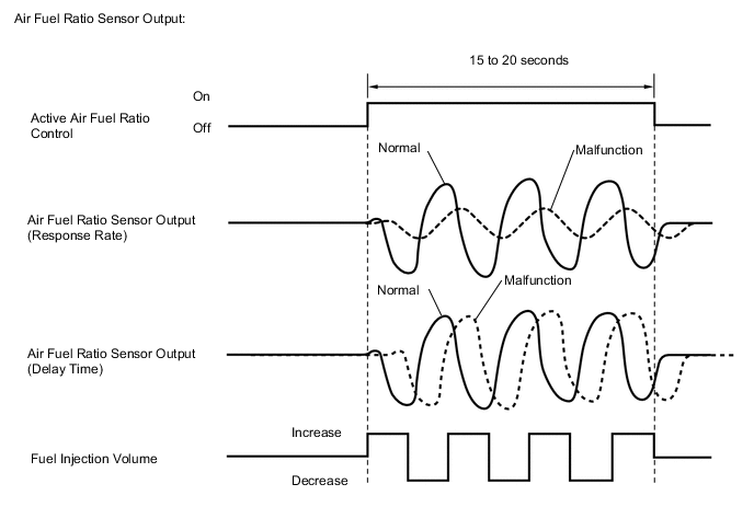
After the engine has been warmed up, the ECM carries out air fuel ratio feedback control and maintains the air fuel ratio at the stoichiometric level. In addition, after all the preconditions have been met, active air fuel ratio control is carried out for approximately 15 to 20 seconds, and during active air fuel ratio control, the ECM measures the response of the air fuel ratio sensor by increasing or decreasing the injection volume by a specific quantity based on the stoichiometric air fuel ratio learned during normal air fuel control. The ECM determines whether there is an air fuel ratio sensor malfunction at the mid-point of active air fuel ratio control.
If the air fuel ratio sensor's response ability is reduced, DTC P014C and P014D are stored.
If the time it takes the air fuel ratio sensor output to change is delayed, DTC P015A and P015B are stored.
MONITOR STRATEGY
| Required Sensors/Components (Main) | Air fuel ratio sensor |
| Frequency of Operation | Once per driving cycle |
TYPICAL ENABLING CONDITIONS
| Active air fuel ratio control | Performing |
| Active air fuel ratio control is performed when the following conditions met | - |
| Engine coolant temperature | 73°C (163°F) or higher |
| Idle | Off |
| Engine speed | 1000 rpm or higher, and less than 4000 rpm |
| Air fuel ratio sensor status | Activated |
| Engine load | 10% or higher, and less than 70% |
| Catalyst monitor | Not yet |
| Mass air flow | 4.5 gm/sec. or more, and less than 12.0 gm/sec. |
CONFIRMATION DRIVING PATTERN
Tech Tips
Performing this confirmation pattern will activate the air fuel ratio sensor response monitor.
-
Connect the GTS to the DLC3.
-
Turn the power switch on (IG).
-
Turn the GTS on.
-
Clear the DTCs (even if no DTCs are stored, perform the clear DTC procedure).
-
Turn the power switch off and wait for at least 30 seconds.
-
Turn the power switch on (IG) and turn the GTS on.
-
Put the engine in inspection mode (maintenance mode).
-
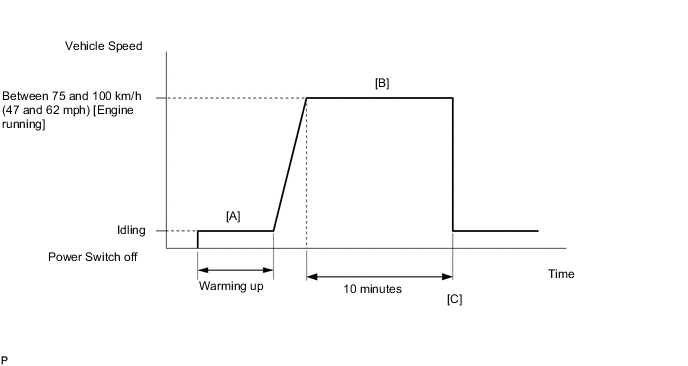
Start the engine and warm it up (until the engine coolant temperature is 73°C (163°F) or higher) [A].
-
With the engine running, drive the vehicle at a constant speed between 75 and 100 km/h (47 and 62 mph) for 10 minutes [B].
CAUTION:
When performing the confirmation driving pattern, obey all speed limits and traffic laws.
Tech Tips
If the engine stops, further depress the accelerator pedal to restart the engine.
-
Enter the following menus: Powertrain / Engine and ECT / Trouble Codes [C].
-
Read the pending DTCs.
Tech Tips
-
If a pending DTC is output, the system is malfunctioning.
-
If a pending DTC is not output, perform the following procedure.
-
-
Enter the following menus: Powertrain / Engine and ECT / Utility / All Readiness.
-
Input the DTC: P014C, P014D, P015A or P015B.
-
Check the DTC judgment result.
GTS Display Description NORMAL
-
DTC judgment completed
-
System normal
ABNORMAL
-
DTC judgment completed
-
System abnormal
INCOMPLETE
-
DTC judgment not completed
-
Perform driving pattern after confirming DTC enabling conditions
N/A
-
Unable to perform DTC judgment
-
Number of DTCs which do not fulfill DTC preconditions has reached ECU memory limit
Tech Tips
-
If the judgment result shows NORMAL, the system is normal.
-
If the judgment result shows ABNORMAL, the system has a malfunction.
-
CAUTION / NOTICE / HINT
Note
Inspect the fuses for circuits related to this system before performing the following procedure.
Tech Tips
-
A low air fuel ratio sensor voltage could be caused by a rich air fuel mixture. Check for conditions that would cause the engine to run rich.
-
A high air fuel ratio sensor voltage could be caused by a lean air fuel mixture. Check for conditions that would cause the engine to run lean.
-
Sensor 1 refers to the sensor closest to the engine assembly.
-
Sensor 2 refers to the sensor farthest away from the engine assembly.
-
Read freeze frame data using the GTS. The ECM records vehicle and driving condition information as freeze frame data the moment a DTC is stored. When troubleshooting, freeze frame data can be helpful in determining whether the vehicle was moving or stationary, whether the engine was warmed up or not, whether the air fuel ratio was lean or rich, as well as other data recorded at the time of a malfunction.
PROCEDURE
-
CHECK ANY OTHER DTCS OUTPUT (IN ADDITION TO DTC P014C, P014D, P015A OR P015B)
-
Connect the GTS to the DLC3.
-
Turn the power switch on (IG).
-
Turn the GTS on.
-
Enter the following menus: Powertrain / Engine and ECT / Trouble Codes.
-
Read the DTCs.
Powertrain > Engine and ECT > Trouble CodesResult Result Proceed to DTC P014C, P014D, P015A or P015B is output A DTC P014C, P014D, P015A or P015B and other DTCs are output B Tech Tips
If any DTCs other than P014C, P014D, P015A or P015B are output, troubleshoot those DTCs first.
B 
GO TO DTC CHART Click here
A 
-
-
INSPECT AIR FUEL RATIO SENSOR (HEATER RESISTANCE)
Result Proceed to OK NG
-
Inspect the air fuel ratio sensor.
Result Proceed to OK NG
NG
REPLACE AIR FUEL RATIO SENSOR Click here
OK
-
-
CHECK HARNESS AND CONNECTOR (AIR FUEL RATIO SENSOR - ECM)
Result Proceed to OK NG
-
Disconnect the air fuel ratio sensor connector.
-
Disconnect the ECM connector.
-
Measure the resistance according to the value(s) in the table below.
Standard Resistance Tester Connection Condition Specified Condition C5-1 (HA1A) - C48-23 (HA1A) Always Below 1 Ω C5-3 (A1A+) - C48-133 (A1A+) Always Below 1 Ω C5-4 (A1A-) - C48-134 (A1A-) Always Below 1 Ω C5-1 (HA1A) or C48-23 (HA1A) - Body ground Always 10 kΩ or higher C5-3 (A1A+) or C48-133 (A1A+) - Body ground Always 10 kΩ or higher C5-4 (A1A-) or C48-134 (A1A-) - Body ground Always 10 kΩ or higher Result Proceed to OK NG
NG
REPAIR OR REPLACE HARNESS OR CONNECTOR
OK
-
-
CHECK AIR FUEL RATIO SENSOR
-
Check that the proper air fuel ratio sensor is installed to the vehicle.
Result Proceed to OK NG
NG
REPLACE AIR FUEL RATIO SENSOR Click here
OK
-
-
PERFORM CONFIRMATION DRIVING PATTERN
-
Drive the vehicle according to Confirmation Driving Pattern.
Result Proceed to NEXT
NEXT
-
-
CHECK WHETHER DTC OUTPUT RECURS (DTC P014C, P014D, P015A OR P015B)
-
Connect the GTS to the DLC3.
-
Turn the power switch on (IG).
-
Turn the GTS on.
-
Enter the following menus: Powertrain / Engine and ECT / Trouble Codes / Pending.
-
Read the pending DTCs.
Powertrain > Engine and ECT > Trouble CodesResult Result Proceed to DTC P014C, P014D, P015A or P015B is output A DTCs are not output B
B
CHECK FOR INTERMITTENT PROBLEMS Click here
A
-
-
REPLACE AIR FUEL RATIO SENSOR
-
Replace the air fuel ratio sensor.
Result Proceed to NEXT
NEXT
-
-
PERFORM CONFIRMATION DRIVING PATTERN
-
Drive the vehicle according to Confirmation Driving Pattern.
Result Proceed to NEXT
NEXT
-
-
CHECK WHETHER DTC OUTPUT RECURS (DTC P014C, P014D, P015A OR P015B)
-
Connect the GTS to the DLC3.
-
Turn the power switch on (IG).
-
Turn the GTS on.
-
Enter the following menus: Powertrain / Engine and ECT / Trouble Codes / Pending.
-
Read the pending DTCs.
Powertrain > Engine and ECT > Trouble CodesResult Result Proceed to DTCs are not output A DTC P014C, P014D, P015A or P015B is output B
A
END
B
CHECK ENGINE TO DETERMINE CAUSE OF EXTREMELY RICH OR LEAN ACTUAL AIR FUEL RATIO Click here
-