SFI SYSTEM(w/ EGR System), Diagnostic DTC:P3190, P3191
| DTC Code | DTC Name |
|---|---|
| P3190 | Poor Engine Power |
| P3191 | Engine does not Start |
DESCRIPTION
The ECM receives signals from the hybrid vehicle control ECU such as the requested engine torque, target engine speed and engine cranking status, and controls the engine output based on the target engine speed and requested torque.
| DTC No. | Detection Item | DTC Detection Condition | Trouble Area | MIL | Memory |
|---|---|---|---|---|---|
| P3190 | Poor Engine Power | When all of the following conditions are met (1 trip detection logic):
|
|
Comes on | DTC stored |
| P3191 | Engine does not Start | When all of the following conditions are met (1 trip detection logic):
|
|
Comes on | DTC stored |
MONITOR DESCRIPTION
-
The ECM receives signals such as requested engine torque, target engine speed and engine cranking status from the hybrid vehicle control ECU.
-
The ECM controls engine start and stop and throttle valve angle based on the signals received from the hybrid vehicle control ECU.
-
The ECM receives the actual engine torque calculated by the hybrid vehicle control ECU based on the generator torque.
-
When the actual engine torque is less than 20% of the requested engine torque*, the ECM judges that the engine output is abnormal and stores DTC P3190.
(The engine may not have started in the above situation.)
-
*: Requested torque = Requested Engine Torque (kW) / HV Target Engine Speed (rpm) x 9549
-
If the ECM does not detect engine start torque (actual engine torque) even though it has received an engine start request and started the engine, it stores DTC P3191.
Tech Tips
-
When DTCs P3190, P3191 and P3193 are output, the engine may be stopped due to the engine condition.
At this time, after adding fuel or performing repairs, clear the DTCs. Then turn the power switch off to return to the normal condition.
-
When this DTC is output and the engine is stopped, the HV battery cannot be charged since the vehicle is driven with the motor only. If the vehicle continues to be driven under this condition, the HV battery becomes depleted ultimately and the power switch cannot be turned on (READY).
-
When DTC P3190 or P3191 is stored, the engine torque has dropped by 80% or the engine cannot be started. If any DTCs that indicate malfunctioning of engine related parts are stored at the same time, repair the malfunctioning parts first.
Relevant Data List Items:
ECM (Powertrain / Engine and ECT / Data List) HV Target Engine Speed Engine Speed Requested Engine Torque Actual Engine Torque Throttle Position Command Throttle Position No.1 Calculate Load Coolant Temp Short FT #1 Long FT #1 EGR Step Position - HYBRID VEHICLE CONTROL ECU (Powertrain / Hybrid Control / Data List) Target Engine Rev Engine Revolution Request Power Engine Coolant Temp Engine Idling Request - - -
-
MONITOR STRATEGY
| Frequency of Operation | Continuous |
CONFIRMATION DRIVING PATTERN
Note
If the MIL (malfunction indicator lamp) or warning light illuminates, immediately end the confirmation driving pattern. If DTCs P3190, P3191 and P3193 are output and the engine is stopped, the HV battery will no longer be chargeable and the distance that the vehicle can be driven will be limited.
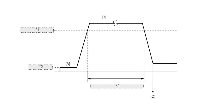
| *1 | 40 km/h (25 mph) [Engine running] |
| *2 | Power Switch on (READY) |
| *3 | Total engine operation time of 10 minutes or more |
-
Apply the parking brake firmly.
-
Connect the GTS to the DLC3.
-
Turn the power switch on (IG) and turn the GTS on.
-
Clear the DTCs (even if no DTCs are stored, perform the clear DTC procedure).
-
Turn the power switch off and wait for at least 30 seconds.
-
Turn the power switch on (READY) and turn the GTS on.
-
Fully depress the accelerator pedal for 10 seconds with the vehicle stopped, park (P) selected and the brake pedal depressed [A].
Note
As soon as the engine starts, release the accelerator pedal.
-
Release the parking brake.
-
Drive the vehicle at an average of approximately 40 km/h (25 mph) or more until the total engine operation time is 10 minutes or more [B].
CAUTION:
When performing the confirmation driving pattern, obey all speed limits and traffic laws.
Tech Tips
-
It is not necessary to maintain the vehicle speed at 40 km/h (25 mph) throughout the road test.
-
If the engine stops, further depress the accelerator pedal to restart the engine.
-
-
Enter the following menus: Powertrain / Engine and ECT / Trouble Codes [C].
-
Read the DTCs (including pending DTCs).
Tech Tips
-
If a DTC (include pending DTC) is output, the system is malfunctioning.
-
If a DTC (include pending DTC) is not output, perform the following procedure.
-
-
Enter the following menus: Powertrain / Engine and ECT / Utility / All Readiness.
-
Input the DTC: P3190 or P3191.
-
Check the DTC judgment result.
GTS Display Description NORMAL
-
DTC judgment completed
-
System normal
ABNORMAL
-
DTC judgment completed
-
System abnormal
INCOMPLETE
-
DTC judgment not completed
-
Perform driving pattern after confirming DTC enabling conditions
N/A
-
Unable to perform DTC judgment
-
Number of DTCs which do not fulfill DTC preconditions has reached ECU memory limit
Tech Tips
If the judgment result shows INCOMPLETE or N/A, perform the Confirmation Driving Pattern and check the DTC judgment result again.
-
CAUTION / NOTICE / HINT
Tech Tips
-
Repeating this inspection for symptom confirmation may cause the SOC to drop, preventing the system from entering the READY-on state. In this case, use the THS charger to charge the HV battery.
-
Cranking the engine once causes the SOC to drop approximately 1%.
-
Charging the HV battery once (10 minutes) using the THS charger restores the SOC approximately 2%.
-
Charging the HV battery using the THS charger takes approximately 10 minutes when the HV battery temperature is 25°C (77°F) or approximately 30 minutes when the HV battery temperature is 0°C (32°F).
-
The THS charger is a supplemental charging device that charges the HV battery enough to enable the engine to start (the vehicle can enter the READY-on state).
-
Read freeze frame data using the GTS. The ECM records vehicle and driving condition information as freeze frame data the moment a DTC is stored. When troubleshooting, freeze frame data can help determine if the vehicle was moving or stationary, if the engine was warmed up or not, if the air fuel ratio was lean or rich, and other data from the time the malfunction occurred.
PROCEDURE
-
CHECK ANY OTHER DTCS OUTPUT (IN ADDITION TO DTC P3190, P3191 AND/OR P3193)
-
Connect the GTS to the DLC3.
-
Turn the power switch on (IG).
-
Turn the GTS on.
-
Enter the following menus: Powertrain / Engine and ECT / Trouble Codes.
-
Check the DTCs and freeze frame data, and then write them down.
Powertrain > Engine and ECT > Trouble CodesResult Result Proceed to DTC P3190 or P3191 are output A DTC P3193 is output B DTC P3190, P3191 and/or P3193 and other DTCs are output C Tech Tips
If any SFI system DTCs other than DTC P3190, P3191 or P3193 is output, perform troubleshooting for those DTCs first.
B 
GO TO DTC P3193 Click here
C
GO TO DTC CHART Click here
A 
-
-
CHECK SHORTAGE OF FUEL
-
Check the amount of fuel remaining.
OK There is enough fuel. Tech Tips
-
DTCs P3190, P3191 and/or P3193 may be output if the vehicle ran out of fuel in the past.
-
If not enough fuel is added, DTC P3190, P3191 or P3193 may be output again. If the engine cannot be started because the vehicle is out of fuel, add fuel until the fuel level warning light turns off.
Result Proceed to OK NG -
NG
REFILL FUEL
OK
-
-
CLEAR DTC
-
Connect the GTS to the DLC3.
-
Turn the power switch on (IG).
-
Turn the GTS on.
-
Clear the DTCs.
Powertrain > Engine and ECT > Clear DTCs -
Turn the power switch off and wait for at least 30 seconds.
Result Proceed to NEXT
NEXT
-
-
CHECK INTAKE SYSTEM
-
Check the intake system for vacuum leaks.
OK No leaks in intake system. Tech Tips
Perform "Inspection After Repair" after repairing or replacing the intake system.
Result Proceed to OK NG
NG
REPAIR OR REPLACE INTAKE SYSTEM
OK
-
-
CHECK FOR UNUSUAL NOISE OR VIBRATION WHEN STARTING ENGINE OR REVVING UP
OK Unusual noise and vibration do not occur. Result Proceed to OK NG
NG
REPAIR OR REPLACE MALFUNCTIONING PARTS
OK
-
CHECK FUEL PRESSURE
-
Check the fuel pressure.
Result Proceed to OK NG
NG
CHECK FUEL PUMP CONTROL CIRCUIT Click here
OK
-
-
INSPECT THROTTLE BODY WITH MOTOR ASSEMBLY
-
Inspect the throttle body with motor assembly.
Tech Tips
Perform "Inspection After Repair" after replacing the throttle body with motor assembly.
Result Proceed to OK NG
NG
REPLACE THROTTLE BODY WITH MOTOR ASSEMBLY Click here
OK
-
-
INSPECT MASS AIR FLOW METER SUB-ASSEMBLY
-
Inspect the mass air flow meter sub-assembly.
Tech Tips
Perform "Inspection After Repair" after replacing the mass air flow meter sub-assembly.
Result Proceed to OK NG
NG
REPLACE MASS AIR FLOW METER SUB-ASSEMBLY Click here
OK
-
-
INSPECT ENGINE COOLANT TEMPERATURE SENSOR
-
Inspect the engine coolant temperature sensor.
Tech Tips
Perform "Inspection After Repair" after replacing the engine coolant temperature sensor.
Result Proceed to OK NG
NG
REPLACE ENGINE COOLANT TEMPERATURE SENSOR Click here
OK
-
-
INSPECT CRANKSHAFT POSITION SENSOR
-
Inspect the crankshaft position sensor.
Result Proceed to OK NG
NG
REPLACE CRANKSHAFT POSITION SENSOR Click here
OK
-
-
PERFORM ACTIVE TEST USING GTS (CONTROL THE EGR STEP POSITION)
-
Connect the GTS to the DLC3.
-
Turn the power switch on (IG).
-
Turn the GTS on.
-
Put the engine in inspection mode (maintenance mode).
Powertrain > Hybrid Control > UtilityTester Display Inspection Mode -
Start the engine and warm it up until the engine coolant temperature reaches 75°C (167°F) or higher.
Tech Tips
The A/C switch and all accessory switches should be off.
-
Enter the following menus: Powertrain / Engine and ECT / Active Test / Control the EGR Step Position / Primary / MAP and Throttle Idle Position.
Powertrain > Engine and ECT > Active TestActive Test Display Control the EGR Step Position Data List Display MAP Throttle Idle Position -
Confirm that the Throttle Idle Position is ON and check the MAP values in the Data List while performing the Active Test.
Tech Tips
-
Do not leave the EGR valve open for 10 seconds or more during the Active Test.
-
Be sure to return the EGR valve to step 0 when the Active Test is completed.
-
Do not open the EGR valve 30 steps or more during the Active Test.
OK MAP change in response to EGR step position when Throttle Idle Position is ON in Data List. Standard - EGR Step Position (Active Test) 0 Steps 0 to 30 Steps MAP
(Data List)
(EGR valve is fully closed) MAP value is at least +10 kPa (75 mmHg) higher than when EGR valve is fully closed Tech Tips
-
While performing the Active Test, if the increase in the value of MAP is small, the EGR valve assembly may be a malfunctioning.
-
Even if the EGR valve assembly is malfunctioning, rough idling or an increase in the value of MAP may occur while performing the Active Test. However, the amount that the value of MAP increases will be smaller than normal.
-
If there are starting problems and the Active Test cannot be performed, perform the EGR valve assembly inspection in the next step.
Result Proceed to OK NG -
OK 
GO TO STEP 13 Click here
NG
-
-
INSPECT EGR VALVE ASSEMBLY
-
Remove the EGR valve assembly.
-
Check if the EGR valve is stuck open.
OK EGR valve is tightly closed. Result Proceed to OK NG
NG
REPLACE EGR VALVE ASSEMBLY Click here
OK
-
-
REPLACE CAMSHAFT POSITION SENSOR
-
Replace the camshaft position sensor.
Result Proceed to NEXT
NEXT
-
-
CHECK WHETHER DTC OUTPUT RECURS (DTC P3190 OR P3191)
-
Connect the GTS to the DLC3.
-
Turn the power switch on (IG).
-
Turn the GTS on.
-
Clear the DTCs.
Powertrain > Engine and ECT > Clear DTCs -
Turn the power switch off and wait for at least 30 seconds.
-
Turn the power switch on (READY).
-
Turn the GTS on.
-
Drive the vehicle in accordance with the driving pattern described in Confirmation Driving Pattern.
-
Enter the following menus: Powertrain / Engine and ECT / Trouble Codes.
-
Read the DTCs.
Powertrain > Engine and ECT > Trouble CodesResult Result Proceed to DTC P3190 or P3191 is output A DTCs are not output B
B
END
A
-
-
REPLACE ECM
-
Replace the ECM.
Result Proceed to NEXT
NEXT
-
-
CONFIRM WHETHER MALFUNCTION HAS BEEN SUCCESSFULLY REPAIRED
-
Connect the GTS to the DLC3.
-
Turn the power switch on (IG).
-
Turn the GTS on.
-
Clear the DTCs.
Powertrain > Engine and ECT > Clear DTCs -
Turn the power switch off and wait for 30 seconds.
-
Turn the power switch on (READY).
-
Turn the GTS on.
-
Drive the vehicle in accordance with the driving pattern described in Confirmation Driving Pattern.
-
Enter the following menus: Powertrain / Engine and ECT / Trouble Codes.
-
Read the DTCs.
Powertrain > Engine and ECT > Trouble CodesResult Proceed to NEXT
NEXT
END
-