FUEL TANK(w/o Canister Pump Module) INSTALLATION
PROCEDURE
-
INSTALL FUEL EVAPORATION TUBE SUB-ASSEMBLY
-
Install the fuel evaporation tube sub-assembly to the fuel tank assembly.
-
-
INSTALL NO. 4 FUEL TUBE CLAMP
-
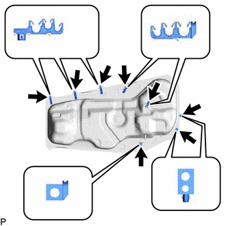
Install the 8 No. 4 fuel tube clamps to the fuel tank assembly as shown in the illustration.
-
-
INSTALL CHARCOAL CANISTER OUTLET TUBE SUB-ASSEMBLY
-
Connect the 3 clamps and install the charcoal canister outlet tube sub-assembly to the 3 No. 4 fuel tube clamps.
-
-
INSTALL NO. 1 FUEL EVAPORATION TUBE SUB-ASSEMBLY
-
Connect the 4 clamps and install the No. 1 fuel evaporation tube sub-assembly to the 4 No. 4 fuel tube clamps.
-
-
INSTALL FUEL TANK MAIN TUBE SUB-ASSEMBLY
-
Connect the 5 clamps and install the fuel tank main tube sub-assembly to the 5 No. 4 fuel tube clamps.
-
-
INSTALL FUEL SENDER GAUGE ASSEMBLY
-
INSTALL FUEL SUCTION TUBE ASSEMBLY
-
INSTALL FUEL TANK VENT TUBE SET PLATE
-
CONNECT FUEL TANK MAIN TUBE SUB-ASSEMBLY
-
CONNECT FUEL EMISSION HOSE
-
INSTALL FUEL TANK ASSEMBLY
-
Set the fuel tank assembly on an engine lifter with attachments.
-
Raise the engine lifter.
Note
Be careful not to cut the wiring.
-
Install the wire harness to the 3 No. 4 fuel tube clamps.
-
Connect the fuel pump connector and fuel sender gauge assembly connector.
-
Connect the No. 3 fuel tank breather tube sub-assembly to the fuel tank assembly.
-
Install the No. 2 fuel tank band with the 2 bolts.
- Torque:
- 45 N*m { 459 kgf*cm, 33 ft.*lbf }
-
Install the No. 1 fuel tank band with the 2 bolts.
- Torque:
- 45 N*m { 459 kgf*cm, 33 ft.*lbf }
-
Connect the 3 wire harness clamps to the 2 No. 4 fuel tube clamps and the bracket on the vehicle side.
-
-
CONNECT CHARCOAL CANISTER OUTLET TUBE SUB-ASSEMBLY
-
Connect the charcoal canister outlet tube sub-assembly to the fuel tank breather tube, then secure it with the hose clamp.
-
Connect the clamp to the No. 2 fuel tank band.
-
-
CONNECT FUEL TANK TO FILLER PIPE HOSE
-
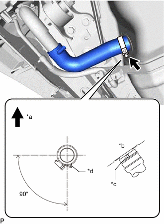
*a Top *b Underside of fuel tank assembly *c Protrusion *d Stopper Connect the fuel tank to filler pipe hose to the fuel tank assembly, then tighten the hose clamp.
Tech Tips
Make sure that the fuel tank to filler pipe hose and hose clamp are oriented as shown in the illustration.
-
-
INSTALL FUEL HOSE PROTECTOR
-
Attach the claw, then install the fuel hose protector to the fuel tank assembly and fuel tank to filler pipe hose.
-
-
CONNECT FUEL TANK MAIN TUBE SUB-ASSEMBLY
-
Connect the fuel tank main tube sub-assembly to the fuel pipe.
-
-
CONNECT NO. 1 FUEL EVAPORATION TUBE
-
Connect the No. 1 fuel evaporation tube to the fuel pipe, then secure the hose clamp.
-
-
INSTALL NO. 2 FLOOR UNDER COVER
-
Install the No. 2 floor under cover with the 2 nuts and attach the clip.
-
-
INSTALL FRONT FLOOR COVER CENTER LH
-
Install the front floor cover center LH with the bolt, 2 nuts and 6 clips.
-
Tighten the nut.
-
-
CONNECT CABLE TO NEGATIVE AUXILIARY BATTERY TERMINAL
Note
When disconnecting the cable, some systems need to be initialized after the cable is reconnected.
-
INSPECT FOR FUEL LEAK