CYLINDER HEAD DISASSEMBLY

PROCEDURE
-
REMOVE INTAKE VALVE
Tech Tips
Type A and type B can be distinguished by the shape of the inner compression spring.
Type Shape of the Inner Compression Spring A Straight B Taper 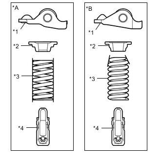
*A Type A *B Type B *1 No. 1 Valve Rocker Arm Sub-assembly *2 Valve Spring Retainer *3 Inner Compression Spring *4 Valve Lash Adjuster Assembly
-
for Type A:
-
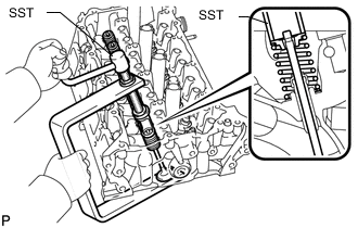
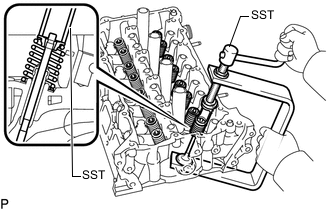
Using SST and wooden blocks, compress the inner compression spring and remove the valve spring retainer locks.
- SST
- 09202-70020 ( 09202-00010 )
-
Remove the valve spring retainer, inner compression spring and intake valve.
Tech Tips
Arrange the removed parts in the correct order.
-
-
for Type B:
-
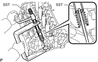
Using SST and wooden blocks, compress the inner compression spring and remove the valve spring retainer locks.
- SST
- 09202-70020
- 09202-00021
-
Remove the valve spring retainer, inner compression spring and intake valve.
Tech Tips
Arrange the removed parts in the correct order.
-
-
-
REMOVE EXHAUST VALVE
Tech Tips
Type A and type B can be distinguished by the shape of the inner compression spring.
Type Shape of the Inner Compression Spring A Straight B Taper
*A Type A *B Type B *1 No. 1 Valve Rocker Arm Sub-assembly *2 Valve Spring Retainer *3 Inner Compression Spring *4 Valve Lash Adjuster Assembly
-
for Type A:
-
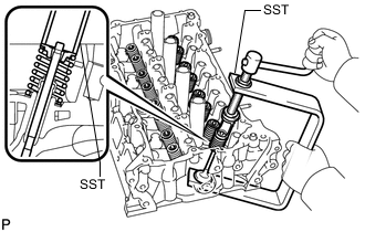
Using SST and wooden blocks, compress the inner compression spring and remove the valve spring retainer locks.
- SST
- 09202-70020 ( 09202-00010 )
-
Remove the valve spring retainer, inner compression spring and exhaust valve.
Tech Tips
Arrange the removed parts in the correct order.
-
-
for Type B:
-
Using SST and wooden blocks, compress the inner compression spring and remove the valve spring retainer locks.
- SST
- 09202-70020
- 09202-00021
-
Remove the valve spring retainer, inner compression spring and exhaust valve.
Tech Tips
Arrange the removed parts in the correct order.
-
-
-
REMOVE VALVE STEM OIL SEAL
-
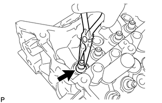
Using needle-nose pliers, remove the valve stem oil seals.
-
-
REMOVE VALVE SPRING SEAT
-
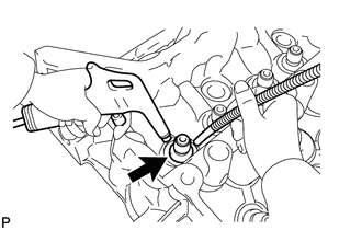
Using compressed air and a magnet hand, remove the valve spring seat by blowing air onto it.
-
-
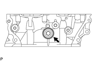
REMOVE NO. 1 STRAIGHT SCREW PLUG
Note
If coolant leaks from a No. 1 straight screw plug or a plug is corroded, replace it.
-
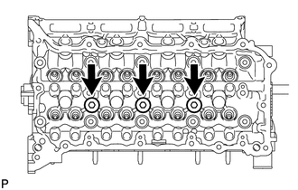
Using a 10 mm hexagon wrench, remove the 3 No. 1 straight screw plugs and 3 gaskets.
-
-
REMOVE NO. 2 STRAIGHT SCREW PLUG
Note
If coolant leaks from the No. 2 straight screw plug or the plug is corroded, replace it.
-
Using a 14 mm hexagon wrench, remove the No. 2 straight screw plug and gasket.
-
-
REMOVE CYLINDER HEAD STUD BOLT
Note
If a stud bolt is deformed or its threads are damaged, replace it.