ENGINE UNIT INSTALLATION

PROCEDURE
-
INSTALL IGNITION COIL ASSEMBLY
-
INSTALL SENSOR WIRE
-
Install the sensor wire with the bolt.
- Torque:
- 21 N*m { 214 kgf*cm, 15 ft.*lbf }
-
Connect the knock control sensor connector.
-
-
INSTALL INJECTOR VIBRATION INSULATOR
-
INSTALL FUEL DELIVERY PIPE
-
INSTALL INTAKE MANIFOLD
-
Install a new No. 1 intake manifold to head gasket to the intake manifold.
-
Temporarily install the intake manifold with the 6 bolts.
-
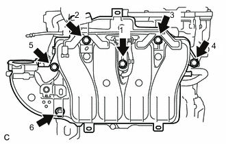
Tighten the 6 bolts in the order shown in the illustration.
- Torque:
- 21 N*m { 214 kgf*cm, 15 ft.*lbf }
-
Connect the purge line hose to the intake manifold, and slide the clamp to secure the hose.
-
Connect the No. 2 PCV hose to the intake manifold, and slide the clamp to secure the hose.
-
-
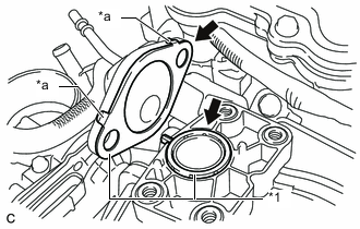
INSTALL WATER INLET HOUSING
-
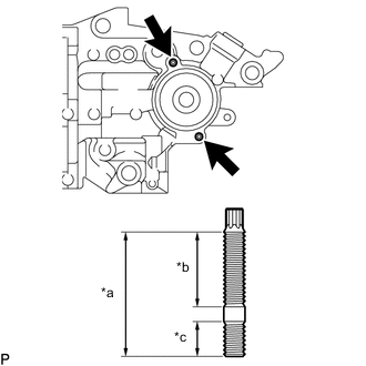
*a 34 mm (1.34 in.) *b 21 mm (0.827 in.) *c 9.0 mm (0.354 in.) Using an E6 "TORX" socket wrench, install the 2 stud bolts to the water inlet housing.
- Torque:
- 4.4 N*m { 45 kgf*cm, 39 in.*lbf }
Note
If a stud bolt is deformed or its threads are damaged, replace it.
-
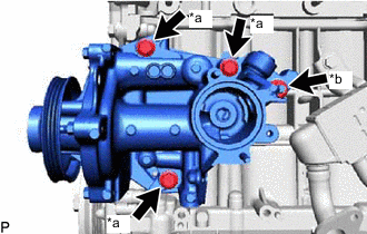
*a Bolt *b Nut Install a new gasket and water inlet housing with the 3 bolts and nut.
- Torque:
- 43 N*m { 438 kgf*cm, 32 ft.*lbf }
-
-
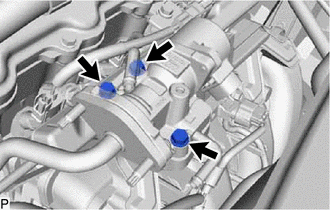
INSTALL OIL COOLER ASSEMBLY (w/ Oil Cooler)
-
INSTALL THERMOSTAT
-
INSTALL WATER INLET
-
INSTALL ENGINE WATER PUMP ASSEMBLY
-
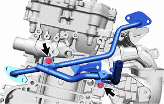
INSTALL NO. 3 WATER BY-PASS PIPE (w/o EGR System)
-
Install the No. 3 water by-pass pipe with the 2 bolts.
- Torque:
- 21 N*m { 214 kgf*cm, 15 ft.*lbf }
-
-
TEMPORARILY INSTALL NO. 1 EGR PIPE (w/ EGR System)
-
Temporarily install the No. 1 EGR pipe with the 2 bolts.
-
-
INSTALL NO. 1 WATER BY-PASS HOSE (w/ EGR System)
-
Install the No. 1 water by-pass hose to the cylinder block, and slide the hose clamp to secure the hose.
-
-
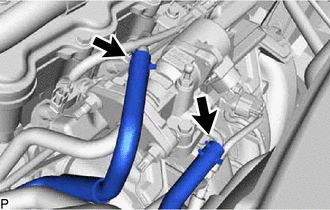
INSTALL NO. 3 WATER BY-PASS HOSE
-
Install the No. 3 water by-pass hose, and slide the hose clamp to secure the hose.
-
-
TEMPORARILY INSTALL EGR VALVE ASSEMBLY (w/ EGR System)
-
*1 Gasket *a Claw Install the new 2 gaskets to the No. 1 EGR pipe and intake manifold.
Note
Make sure that the gasket is installed in the correct direction.
-
Temporarily install the No. 1 EGR valve to the intake manifold with the 3 bolts.
-
Temporarily connect the No. 1 EGR pipe to the EGR valve assembly with the 2 nuts.
-
-
INSTALL NO. 1 WATER BY-PASS PIPE (w/o EGR System)
-
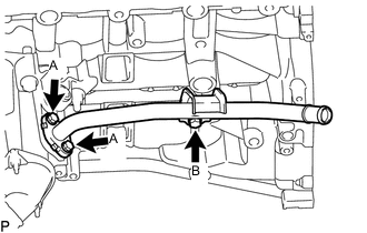
Temporarily install a new gasket and No. 1 water by-pass pipe with the 3 bolts.
-
Tighten the 2 bolts labeled A, and then tighten bolt B.
- Torque:
- for bolt A
- 10 N*m { 102 kgf*cm, 7 ft.*lbf }
- for bolt B
- 21 N*m { 214 kgf*cm, 15 ft.*lbf }
-
-
INSTALL NO. 5 WATER BY-PASS HOSE (w/o EGR System)
-
Install the No. 5 water by-pass hose to the water by-pass pipe and No. 3 water by-pass pipe, and slide the 2 hose clamps to secure the hose.
-
-
TEMPORARILY INSTALL EGR COOLER ASSEMBLY (w/ EGR System)
-
Install the new gasket to the No. 1 EGR pipe.
Note
Make sure that the gasket is installed in the correct direction.
-
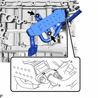
*a Claw Temporarily install the EGR cooler assembly with the nut and bolt.
Tech Tips
The nut and bolt can be installed to either side depending on the position of the stud bolt.
-
Connect the No. 5 water by-pass hose to the EGR cooler assembly, and slide the hose clamp to secure the hose.
-
Temporarily connect the No. 1 EGR pipe to the EGR cooler assembly with the bolt and nut.
-
-
INSTALL WATER BY-PASS PIPE (w/ EGR System)
-
Install the new 2 gaskets and water by-pass pipe with the 4 bolts.
- Torque:
- 10 N*m { 102 kgf*cm, 7 ft.*lbf }
-
-
TIGHTEN NO. 1 EGR PIPE (w/ EGR System)
-
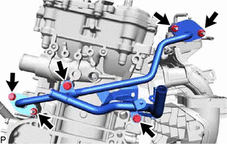
Tighten the 3 bolts and 3 nuts.
- Torque:
- 21 N*m { 214 kgf*cm, 15 ft.*lbf }
-
-
TIGHTEN EGR COOLER ASSEMBLY (w/ EGR System)
-
Tighten the bolt and nut.
- Torque:
- 21 N*m { 214 kgf*cm, 15 ft.*lbf }
-
-
TIGHTEN EGR VALVE ASSEMBLY (w/ EGR System)
-
Tighten the 3 bolts.
- Torque:
- 10 N*m { 102 kgf*cm, 7 ft.*lbf }
-
Connect the No. 1 water by-pass hose and No. 2 water by-pass hose to the EGR valve assembly, and slide the 2 clamps to secure the hose.
-
-
INSTALL THROTTLE WITH MOTOR BODY ASSEMBLY
-
INSTALL EXHAUST MANIFOLD CONVERTER SUB-ASSEMBLY
-
INSTALL MANIFOLD STAY
-
INSTALL NO. 2 MANIFOLD STAY
-
INSTALL NO. 2 EGR PIPE (w/ EGR System)
-
INSTALL NO. 1 EXHAUST MANIFOLD HEAT INSULATOR
-
INSTALL NO. 1 COMPRESSOR MOUNTING BRACKET
-
Install the No. 1 compressor mounting bracket with the 4 bolts.
- Torque:
- 24.5 N*m { 250 kgf*cm, 18 ft.*lbf }
-
-
INSTALL COMPRESSOR ASSEMBLY WITH MOTOR
-
INSTALL V-RIBBED BELT TENSIONER ASSEMBLY
-
Install the V-ribbed belt tensioner assembly with the bolt.
- Torque:
- 21 N*m { 214 kgf*cm, 15 ft.*lbf }
-
-
INSTALL ENGINE OIL LEVEL DIPSTICK GUIDE
-
Apply a light coat of engine oil to a new O-ring.
-
Install the O-ring to the engine oil level dipstick guide.
-
Install the engine oil level dipstick guide with the bolt.
- Torque:
- 10 N*m { 102 kgf*cm, 7 ft.*lbf }
-
Install the engine oil level dipstick.
-