ENGINE ASSEMBLY INSTALLATION
CAUTION / NOTICE / HINT
CAUTION:
As the engine assembly with transaxle is extremely heavy, the engine lifter may suddenly drop if the instructions listed in the repair manual are not followed. Therefore, always follow the instructions listed in the repair manual when performing this procedure.
Tech Tips
Perform "Inspection After Repairs" after replacing the engine assembly, cylinder head sub-assembly, camshaft, No. 2 camshaft, camshaft timing gear assembly, piston or piston ring.
-
w/ EGR System:
-
w/o EGR System:
-
w/ Canister Pump Module:
PROCEDURE
-
INSTALL DRIVE SHAFT BEARING BRACKET
-
Install the drive shaft bearing bracket with the 3 bolts.
- Torque:
- 63.7 N*m { 650 kgf*cm, 47 ft.*lbf }
-
-
INSTALL ENGINE MOUNTING INSULATOR LH
Tech Tips
Perform this procedure only when replacement of the engine mounting insulator LH is necessary.
-
Temporarily install the engine mounting insulator LH with the 4 bolts.
-
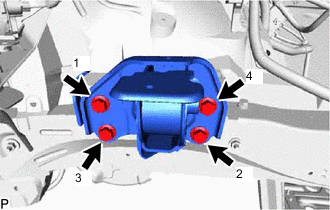
Tighten the 4 bolts in the sequence shown in the illustration.
- Torque:
- 95 N*m { 969 kgf*cm, 70 ft.*lbf }
-
-
INSTALL ENGINE MOUNTING SPACER
Tech Tips
Perform this procedure only when replacement of the engine mounting spacer is necessary.
-
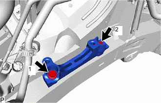
Temporarily install the engine mounting spacer with the 2 bolts.
-
Tighten the 2 bolts in the sequence shown in the illustration.
- Torque:
- 95 N*m { 969 kgf*cm, 70 ft.*lbf }
-
-
INSTALL ENGINE MOUNTING INSULATOR SUB-ASSEMBLY RH
Tech Tips
Perform this procedure only when replacement of the engine mounting insulator sub-assembly RH is necessary.
-
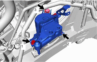
Temporarily install the engine mounting insulator sub-assembly RH with the 3 bolts.
-
Tighten the 3 bolts in the sequence shown in the illustration.
- Torque:
- 95 N*m { 969 kgf*cm, 70 ft.*lbf }
-
Install the radiator reservoir bracket with the bolt.
- Torque:
- 5.0 N*m { 51 kgf*cm, 44 in.*lbf }
-
-
INSTALL REAR ENGINE MOUNTING INSULATOR
Tech Tips
Perform this procedure only when replacement of the rear engine mounting insulator is necessary.
-
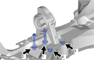
Temporarily install the rear engine mounting insulator with the 2 bolts and 2 nuts.
-
Tighten the 2 bolts and 2 nuts in the sequence shown in the illustration.
- Torque:
- 95 N*m { 969 kgf*cm, 70 ft.*lbf }
-
-
INSTALL ENGINE HANGER
-
REMOVE ENGINE FROM ENGINE STAND
Note
-
Pay attention to the angle of the sling device as the engine assembly or engine hangers may be damaged or deformed if the angle is incorrect.
-
With the exception of installing the engine assembly to an engine stand or removing the engine assembly from an engine stand, do not perform any work on the engine while it is suspended, as doing so is dangerous.
-
Attach a sling device and hang the engine with a chain block.
-
Lift the engine and remove it from the engine stand.
-
-
FIX ENGINE ASSEMBLY
-
INSTALL ENGINE WIRE
-
INSTALL FLYWHEEL SUB-ASSEMBLY
-
INSTALL TRANSMISSION INPUT DAMPER ASSEMBLY
-
INSTALL HYBRID VEHICLE TRANSAXLE ASSEMBLY
-
INSTALL TRANSMISSION OIL COOLER ASSEMBLY
-
CONNECT WIRE HARNESS
-
INSTALL ENGINE ASSEMBLY WITH TRANSAXLE
-
Temporarily install the front engine mounting insulator with the through bolt and nut.
-
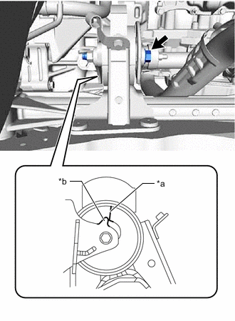
*a Alignment Mark *b Protrusion Temporarily install the front suspension crossmember with the through bolt and nut.
Tech Tips
When installing the suspension crossmember, align the protrusion of the engine mounting bracket with the alignment mark of the engine mounting insulator.
-
Place the engine on an engine lifter.
Tech Tips
Place the engine on wooden blocks or equivalent so that the engine is level.
Note
-
Place the engine on wooden blocks or equivalent so that the engine is level.
-
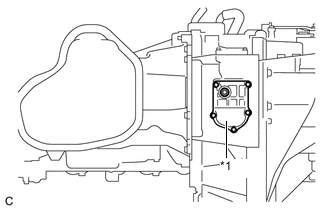
*1 No. 2 Motor Water Jacket Cover Assembly To prevent coolant leaks, do not position the height adjustment attachments or plate lift attachments under the No. 2 motor water jacket cover assembly.
-
-
Operate the engine lifter and install the engine to the vehicle.
CAUTION:
Do not raise the engine more than necessary. If the engine is raised excessively, the vehicle may also be lifted up.
Note
-
Make sure that the engine is clear of all wiring and hoses.
-
While raising the engine into the vehicle, do not allow it to contact the vehicle.
-
-
Temporarily install the front suspension crossmember with the 2 bolts.
-
Temporarily install the front suspension member rear brace RH and front suspension member rear brace LH with the 6 bolts.
-
Install the engine mounting insulator LH with the through bolt and nut.
- Torque:
- 56 N*m { 571 kgf*cm, 41 ft.*lbf }
Note
While holding the through bolt in place, tighten the nut.
-
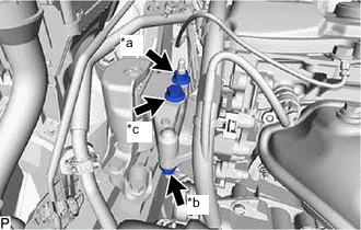
*a Nut A *b Nut B *c Bolt Install the engine mounting insulator RH with the bolt and 2 nuts.
- Torque:
- for bolt and nut A
- 95 N*m { 969 kgf*cm, 70 ft.*lbf }
- for nut B
- 52 N*m { 530 kgf*cm, 38 ft.*lbf }
-
Tighten the 2 bolts.
- Torque:
- 137 N*m { 1397 kgf*cm, 101 ft.*lbf }
-
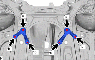
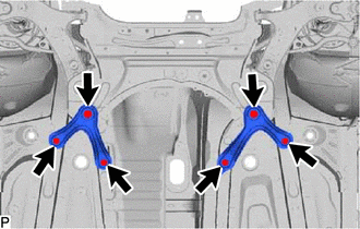
*a Bolt A *b Bolt B Tighten the 6 bolts.
- Torque:
- for bolt A
- 137 N*m { 1397 kgf*cm, 101 ft.*lbf }
- for bolt B
- 93 N*m { 948 kgf*cm, 69 ft.*lbf }
-
Remove the 2 bolts and 2 engine hangers.
-
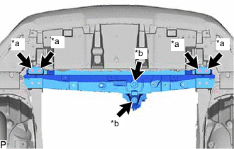
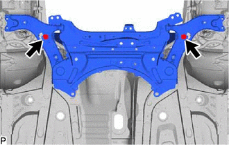
*a Bolt A *b Bolt B Install the front crossmember with the 6 bolts.
- Torque:
- for bolt A
- 99 N*m { 1010 kgf*cm, 73 ft.*lbf }
- for bolt B
- 95 N*m { 969 kgf*cm, 70 ft.*lbf }
-
While holding the nut in place, tighten the through bolt of the rear engine mounting insulator.
- Torque:
- 95 N*m { 969 kgf*cm, 70 ft.*lbf }
Tech Tips
Check that the protrusion of the engine mounting bracket is aligned with the alignment mark of the engine mounting insulator.
-
Tighten the through bolt and nut of the front engine mounting insulator.
- Torque:
- 145 N*m { 1479 kgf*cm, 107 ft.*lbf }
Note
While holding the nut in place, tighten the through bolt.
-
-
INSTALL FRONT SUSPENSION MEMBER REINFORCEMENT LH
-
INSTALL FRONT SUSPENSION MEMBER REINFORCEMENT RH
-
INSTALL FRONT EXHAUST PIPE ASSEMBLY
-
INSTALL FLYWHEEL HOUSING UNDER COVER
-
Install the flywheel housing under cover.
-
-
INSTALL FRONT DRIVE SHAFT HOLE SNAP RING LH
-
INSTALL FRONT DRIVE SHAFT ASSEMBLY LH
-
INSTALL FRONT DRIVE SHAFT ASSEMBLY RH
-
CONNECT FRONT LOWER NO. 1 SUSPENSION ARM SUB-ASSEMBLY LH
-
CONNECT FRONT LOWER NO. 1 SUSPENSION ARM SUB-ASSEMBLY RH
Tech Tips
Use the same procedure described for the LH side.
-
CONNECT TIE ROD END SUB-ASSEMBLY LH
-
CONNECT TIE ROD END SUB-ASSEMBLY RH
Tech Tips
Use the same procedure described for the LH side.
-
CONNECT FRONT STABILIZER LINK ASSEMBLY LH
-
CONNECT FRONT STABILIZER LINK ASSEMBLY RH
Tech Tips
Use the same procedure described for the LH side.
-
CONNECT FRONT SPEED SENSOR LH
-
w/ AVS:
-
w/o AVS:
-
-
CONNECT FRONT SPEED SENSOR RH
Tech Tips
Use the same procedure described for the LH side.
-
INSTALL FRONT AXLE SHAFT NUT LH
-
INSTALL FRONT AXLE SHAFT NUT RH
Tech Tips
Use the same procedure described for the LH side.
-
CONNECT NO. 1 STEERING COLUMN HOLE COVER SUB-ASSEMBLY
-
CONNECT NO. 2 STEERING INTERMEDIATE SHAFT ASSEMBLY
-
INSTALL COLUMN HOLE COVER SILENCER SHEET
-
CONNECT TRANSMISSION CONTROL CABLE ASSEMBLY
-
Connect the transmission control cable assembly to the control shaft lever with the nut.
- Torque:
- 12 N*m { 122 kgf*cm, 9 ft.*lbf }
-
Connect the transmission control cable assembly to the control cable bracket with a new clip.
-
Connect the transmission control cable assembly to the hybrid transaxle assembly with the bolt.
- Torque:
- 12 N*m { 122 kgf*cm, 9 ft.*lbf }
-
Connect the transmission control cable assembly to the rear engine mounting insulator with the bolt.
- Torque:
- 5.0 N*m { 51 kgf*cm, 44 in.*lbf }
-
Attach the clamp to connect the transmission control cable assembly to the bracket.
-
-
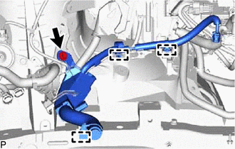
CONNECT HEATER WATER OUTLET HOSE
-
w/ EGR System:
Connect the heater water outlet hose to the No. 1 EGR pipe, and slide the hose clamp to secure the hose.
-
w/o EGR System:
Connect the heater water outlet hose to the No. 3 water by-pass pipe, and slide the hose clamp to secure the hose.
-
-
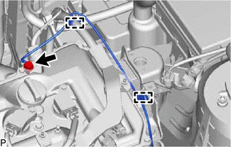
CONNECT HEATER WATER INLET HOSE
-
Connect the heater water inlet hose to the cylinder head sub-assembly, and slide the hose clamp to secure the hose.
-
-
CONNECT FUEL TUBE SUB-ASSEMBLY
-
CONNECT WIRE HARNESS
-
Install the terminal to the No. 1 engine room relay block side cover.
-
Connect the 3 connectors and attach the 2 claws to connect the wire harness to the No. 1 engine room relay block.
-
Install the nut.
- Torque:
- 8.4 N*m { 86 kgf*cm, 74 in.*lbf }
-
Attach the 3 wire harness clamps and connect the wire harness with the bolt.
- Torque:
- 7.7 N*m { 79 kgf*cm, 68 in.*lbf }
-
-
CONNECT GROUND WIRE
-
Connect the ground wire with the bolt and attach the 2 wire harness clamps.
- Torque:
- 29 N*m { 296 kgf*cm, 21 ft.*lbf }
-
-
INSTALL NO. 5 INVERTER COOLING HOSE
-
Install the No. 5 inverter cooling hose to the motor cooling cooler, and slide the hose clip to secure the hose.
-
-
INSTALL NO. 3 INVERTER COOLING HOSE
-
Install the No. 3 inverter cooling hose to the hybrid vehicle transaxle, and slide the hose clip to secure the hose.
-
-
CONNECT SUCTION HOSE SUB-ASSEMBLY
-
CONNECT DISCHARGE HOSE SUB-ASSEMBLY
-
CONNECT NO. 1 RADIATOR HOSE
-
Connect the No. 1 radiator hose to the cylinder head sub-assembly, and slide the hose clip to secure the hose.
-
-
INSTALL RADIATOR HOSE HOSE CLAMP
-
Install the radiator hose hose clamp.
-
-
CONNECT NO. 2 RADIATOR HOSE
-
Connect the No. 2 radiator hose to the water inlet, and slide the hose clip to secure the hose.
-
-
INSTALL FAN AND GENERATOR V BELT
-
CONNECT RADIATOR RESERVOIR ASSEMBLY
-
Connect the radiator reservoir assembly with the 2 bolts.
- Torque:
- 5.0 N*m { 51 kgf*cm, 44 in.*lbf }
-
-
INSTALL ECM
-
INSTALL INVERTER BRACKET ASSEMBLY
-
Temporarily install the inverter bracket assembly with the 5 bolts.
-
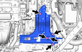
Tighten the 5 bolts in the sequence shown in the illustration.
- Torque:
- 18 N*m { 184 kgf*cm, 13 ft.*lbf }
-
-
INSTALL INVERTER WATER PUMP WITH MOTOR ASSEMBLY
-
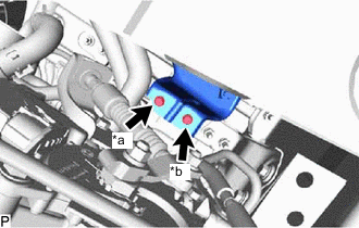
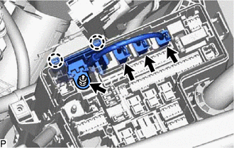
*a Bolt A *b Bolt B Temporarily install the inverter water pump with motor assembly to the inverter bracket with bolt A.
-
Install bolt B.
- Torque:
- 10 N*m { 102 kgf*cm, 7 ft.*lbf }
-
Tighten bolt A.
- Torque:
- 10 N*m { 102 kgf*cm, 7 ft.*lbf }
-
-
CONNECT NO. 2 FLOOR WIRE
CAUTION:
Be sure to wear insulated gloves.
-
Connect the No. 2 floor wire to the hybrid vehicle transaxle assembly with the 2 clamps.
-
Connect the No. 2 floor wire to the inverter bracket with the 2 clamps.
-
Install the bolt.
- Torque:
- 7.7 N*m { 79 kgf*cm, 68 in.*lbf }
-
-
INSTALL INVERTER WITH CONVERTER ASSEMBLY
-
INSTALL AIR CLEANER CASE SUB-ASSEMBLY
-
Install the air cleaner case sub-assembly with the 2 bolts.
- Torque:
- 7.0 N*m { 71 kgf*cm, 62 in.*lbf }
-
-
INSTALL AIR CLEANER FILTER ELEMENT SUB-ASSEMBLY
-
Install the air cleaner filter element sub-assembly.
-
-
INSTALL AIR CLEANER CAP SUB-ASSEMBLY
-
INSTALL SERVICE PLUG GRIP
-
INSTALL HYBRID BATTERY SERVICE PLUG COVER
-
INSTALL BATTERY SERVICE HOLE COVER
-
CONNECT CABLE TO NEGATIVE AUXILIARY BATTERY TERMINAL
-
INSTALL DECK FLOOR BOX LH (w/ Spare Tire)
-
INSTALL REAR DECK FLOOR BOX (w/ Spare Tire)
-
INSTALL NO. 3 DECK BOARD SUB-ASSEMBLY (w/ Spare Tire)
-
ADD ENGINE OIL
-
ADD COOLANT (for Inverter Coolant)
-
ADD HYBRID TRANSAXLE FLUID
-
ADD ENGINE COOLANT
-
CHARGE AIR CONDITIONING SYSTEM WITH REFRIGERANT
-
for HFC-134a (R134a)
-
for HFO-1234yf (R1234yf)
-
-
INSPECT FOR FUEL LEAK
-
INSPECT FOR OIL LEAK
-
INSPECT FOR COOLANT LEAK
-
INSPECT FOR HYBRID TRANSAXLE FLUID
-
INSPECT FOR COOLANT LEAK (for Inverter Coolant)
-
INSPECT ENGINE OIL LEVEL
-
INSPECT ENGINE COOLANT LEVEL
-
INSPECT COOLANT LEVEL IN RESERVOIR TANK (for Inverter Coolant)
-
INSPECT HYBRID TRANSAXLE FLUID
-
INSPECT FOR EXHAUST GAS LEAK
-
INSPECT FOR REFRIGERANT LEAK
-
for HFC-134a (R134a)
-
for HFO-1234yf (R1234yf)
-
-
INSPECT IGNITION TIMING
-
INSPECT ENGINE IDLE SPEED
-
INSPECT CO/HC
-
TEST MODE PROCEDURE (SPEED SENSOR)
-
ADJUST SHIFT LEVER POSITION
-
ADJUST FRONT WHEEL ALIGNMENT
-
INSTALL FRONT FLOOR COVER CENTER LH
-
INSTALL REAR ENGINE UNDER COVER RH
-
Install the rear engine under cover RH with the 2 clips.
-
-
INSTALL REAR ENGINE UNDER COVER LH
-
Install the rear engine under cover LH with the 2 clips.
-
-
INSTALL NO. 1 ENGINE UNDER COVER ASSEMBLY
-
Install the No. 1 engine under cover assembly with the 2 screws, 4 bolts and 10 clips.
-
-
INSTALL RADIATOR SUPPORT OPENING COVER
-
INSTALL NO. 1 ENGINE COVER SUB-ASSEMBLY
-
Align the 3 grommets of the No. 1 engine cover sub-assembly with the 3 pins, and install the No. 1 engine cover sub-assembly by pressing it.
-