CYLINDER HEAD GASKET INSTALLATION
CAUTION / NOTICE / HINT
Tech Tips
Perform "Inspection After Repairs" after replacing the cylinder head sub-assembly.
-
w/ EGR System:
-
w/o EGR System:
-
w/Canister Pump Module:
PROCEDURE
-
INSTALL CYLINDER HEAD GASKET
-
Clean the cylinder block and cylinder head sub-assembly with solvent.
-
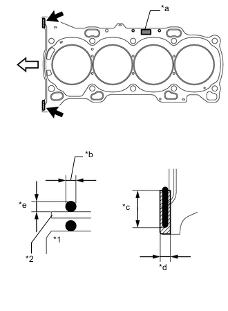
*1 Cylinder Block *2 Cylinder Head Gasket *a Lot No. *b 3.0 to 7.0 mm (0.118 to 0.276 in.) *c 20 mm (0.787 in.) or more *d 7.0 mm (0.276 in.) *e 3.0 mm (0.118 in.) or more 
Seal Packing Application Area 
Engine Front Apply a seal packing to a new cylinder head gasket as shown in the illustration.
Seal packing Toyota Genuine Seal Packing Black, Three Bond 1207B or equivalent Standard seal dimension 3.0 to 7.0 mm (0.118 to 0.276 in.) wide and 3.0 mm (0.118 in.) thick Note
-
Remove any oil from the contact surface.
-
Install the cylinder head gasket within 3 minutes and tighten the bolts within 15 minutes after applying seal packing.
Tech Tips
Apply at least 20 mm (0.787 in.) of seal packing from the inside edge of the protrusion of the cylinder block.
-
-
Place a new cylinder head gasket on the cylinder block surface with the front face of the Lot No. stamp upward.
Note
Pay attention to the installation direction.
-
-
INSTALL CYLINDER HEAD SUB-ASSEMBLY
Tech Tips
Perform "Inspection After Repairs" after replacing the cylinder head sub-assembly.
-
w/ EGR System:
-
w/o EGR System:
-
w/ Canister Pump Module:
-
Place the cylinder head sub-assembly on the cylinder block.
Note
-
Make sure that no oil is on the mounting surface of the cylinder head sub-assembly.
-
Place the cylinder head sub-assembly on the cylinder block gently in order not to damage the gasket with the bottom part of the head.
Tech Tips
The cylinder head set bolts are tightened in 4 progressive steps.
-
-
Install the plate washers to the cylinder head set bolts.
-
Apply a light coat of engine oil to the threads and under the heads of the cylinder head set bolts.
-
Step 1:
-
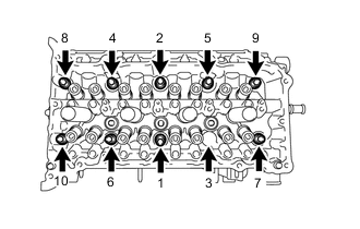
Using a 10 mm bi-hexagon wrench, install and uniformly tighten the 10 cylinder head set bolts in several steps in the sequence shown in the illustration.
- Torque:
- 36 N*m { 367 kgf*cm, 27 ft.*lbf }
Note
Do not drop the plate washers for the cylinder head set bolt into the cylinder head sub-assembly.
-
-
Step 2:
-
Tighten the cylinder head set bolts again in the sequence shown in the illustration to make sure that they are tightened to the specified torque.
- Torque:
- 36 N*m { 367 kgf*cm, 27 ft.*lbf }
-
-
Step 3:
-
Mark the front side of each cylinder head set bolt head with paint.
-
Tighten the cylinder head set bolts 90° in the sequence shown in step 1.
-
-
Step 4:
-
Tighten the cylinder head set bolts another 90° in the sequence shown in step 1.
-
Check that the paint marks are now at a 180° angle to the front.
Note
-
Do not apply oil for at least 4 hours after the installation.
-
Do not start the engine for at least 4 hours after the installation.
-
After the installation, if the seal packing has seeped out, wipe it off.
-
-
-
-
INSTALL VALVE STEM CAP
-
INSTALL VALVE LASH ADJUSTER ASSEMBLY
-
INSTALL NO. 1 VALVE ROCKER ARM SUB-ASSEMBLY
-
INSTALL NO. 2 CAMSHAFT BEARING
-
INSTALL NO. 1 CAMSHAFT BEARING
-
INSTALL NO. 2 CAMSHAFT
-
INSTALL CAMSHAFT
-
INSTALL OIL CONTROL VALVE FILTER
-
INSTALL CAMSHAFT BEARING CAP
-
INSTALL CAMSHAFT HOUSING SUB-ASSEMBLY
-
INSTALL CAMSHAFT TIMING GEAR ASSEMBLY
-
INSTALL CAMSHAFT TIMING SPROCKET
-
ADD ENGINE OIL
-
INSTALL NO. 1 CHAIN VIBRATION DAMPER
-
INSTALL CHAIN SUB-ASSEMBLY
-
INSTALL CHAIN TENSIONER SLIPPER
-
INSTALL NO. 1 CHAIN TENSIONER ASSEMBLY
-
INSTALL TIMING CHAIN GUIDE
-
CHECK NO. 1 CYLINDER TO TDC/COMPRESSION
-
INSTALL INJECTOR VIBRATION INSULATOR
-
INSTALL FUEL DELIVERY PIPE
-
INSTALL INTAKE MANIFOLD
-
INSTALL NO. 3 WATER BY-PASS PIPE (w/o EGR System)
-
TEMPORARILY INSTALL NO. 1 EGR PIPE (w/ EGR System)
-
INSTALL NO. 1 WATER BY-PASS HOSE (w/ EGR System)
-
INSTALL NO. 3 WATER BY-PASS HOSE
-
TEMPORARILY INSTALL EGR VALVE ASSEMBLY (w/ EGR System)
-
INSTALL NO. 1 WATER BY-PASS PIPE (w/o EGR System)
-
INSTALL NO. 5 WATER BY-PASS HOSE (w/o EGR System)
-
TEMPORARILY INSTALL EGR COOLER ASSEMBLY (w/ EGR System)
-
INSTALL WATER BY-PASS PIPE (w/ EGR System)
-
TIGHTEN NO. 1 EGR PIPE (w/ EGR System)
-
TIGHTEN EGR COOLER ASSEMBLY (w/ EGR System)
-
TIGHTEN EGR VALVE ASSEMBLY (w/ EGR System)
-
INSTALL THROTTLE WITH MOTOR BODY ASSEMBLY
-
INSTALL EXHAUST MANIFOLD CONVERTER SUB-ASSEMBLY
-
INSTALL TIMING CHAIN COVER ASSEMBLY