CAMSHAFT REMOVAL
PROCEDURE
-
REMOVE SERVICE PLUG GRIP
-
REMOVE NO. 1 ENGINE COVER SUB-ASSEMBLY
-
REMOVE NO. 1 ENGINE UNDER COVER ASSEMBLY
-
REMOVE REAR ENGINE UNDER COVER RH
-
REMOVE FAN AND GENERATOR V BELT
-
DISCONNECT RADIATOR RESERVOIR ASSEMBLY
-
REMOVE AIR CLEANER CAP SUB-ASSEMBLY
-
REMOVE AIR CLEANER FILTER ELEMENT SUB-ASSEMBLY
-
REMOVE AIR CLEANER CASE SUB-ASSEMBLY
-
DISCONNECT GROUND WIRE
-
DISCONNECT ENGINE WIRE
-
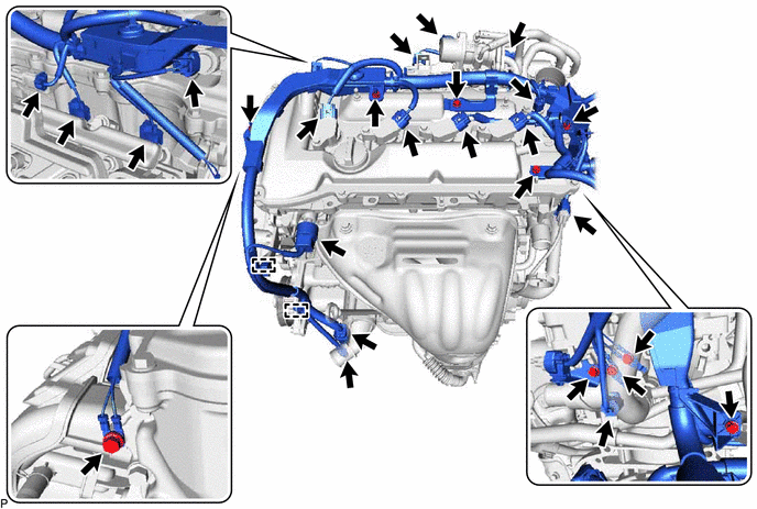
Disconnect the 17 connectors and 2 clamps.
-
Remove the 7 bolts and 3 nuts and disconnect the engine wire from the engine.
-
-
REMOVE IGNITION COIL ASSEMBLY
-
REMOVE CYLINDER HEAD COVER SUB-ASSEMBLY
-
SET NO. 1 CYLINDER TO TDC/COMPRESSION
-
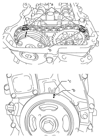
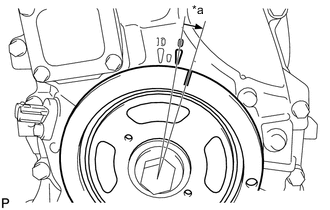
*a Paint Mark *b Timing Mark (Groove) *c Timing Mark "0" Turn the crankshaft until the timing mark (groove) of the crankshaft pulley and the timing mark "0" of the timing chain cover are aligned.
-
Check that each timing mark of the camshaft timing gear assembly and camshaft timing sprocket are located as shown in the illustration. If not, turn the crankshaft 1 revolution (360°) to align the timing marks as shown in the illustration.
-
Place paint marks on the chain sub-assembly in alignment with the timing marks on the camshaft timing gear assembly and camshaft timing sprocket.
-
-
REMOVE TIMING CHAIN COVER PLATE
-
REMOVE NO. 1 CHAIN TENSIONER ASSEMBLY
-

*a Approximately 10° Turn the crankshaft approximately 10° clockwise.
-
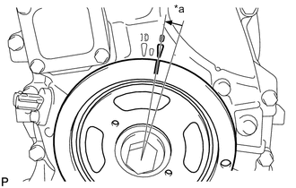
*a Approximately 10° Turn the crankshaft approximately 10° counterclockwise.
-
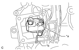
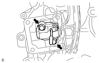
*a Stopper Plate *b Pin Align the holes of the stopper plate and No. 1 chain tensioner assembly, and insert a pin into the stopper plate hole to lock the No. 1 chain tensioner assembly.
-
*a Approximately 10° Turn the crankshaft approximately 10° clockwise.
-
Remove the 2 bolts, No. 1 chain tensioner assembly and gasket.
Note
Make sure not to drop the gasket inside the timing chain cover assembly.
-

*a Approximately 10° Turn the crankshaft approximately 10° counterclockwise.
-
-
REMOVE TIMING CHAIN GUIDE
-
REMOVE TIMING CHAIN COVER TIGHT PLUG
-
REMOVE CAMSHAFT TIMING GEAR ASSEMBLY
-
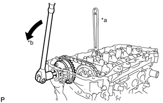
*a Hold *b Turn Hold the hexagonal portion of the camshaft with a wrench and remove the bolt from the camshaft.
Note
Be careful not to damage the camshaft housing sub-assembly or spark plug tube with the wrench.
-
Separate the camshaft timing gear assembly from the camshaft.
-
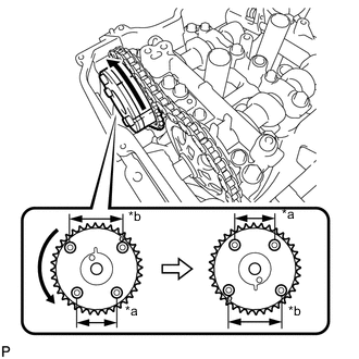
*a Narrow *b Wide Remove the chain sub-assembly from the camshaft timing gear assembly, and turn the camshaft timing gear assembly approximately 180°.
-
Remove the camshaft timing gear assembly.
Note
Do not disassemble the camshaft timing gear assembly.
-
-
REMOVE CAMSHAFT BEARING CAP
-
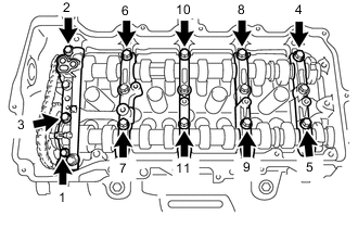
Using several steps, remove the 11 bearing cap bolts in the sequence shown in the illustration.
-
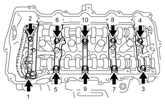
Using several steps, remove the 10 bearing cap bolts in the sequence shown in the illustration.
-
Remove the 5 camshaft bearing caps.
Tech Tips
Arrange the removed parts in the correct order.
-
-
REMOVE CAMSHAFT
-
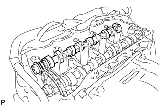
Remove the camshaft from the camshaft housing sub-assembly.
-
-
REMOVE NO. 2 CAMSHAFT
-
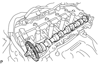
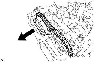
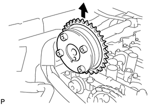
Hold up the chain and remove the No. 2 camshaft from the camshaft housing sub-assembly.
-
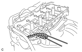
Suspend the chain sub-assembly with a string or equivalent as shown in the illustration.
Note
Be careful not to drop the chain sub-assembly inside the timing chain cover assembly.
-
-
REMOVE CAMSHAFT TIMING SPROCKET
-
Secure the No. 2 camshaft between aluminum plates in a vise.
Note
Do not damage the No. 2 camshaft.
-
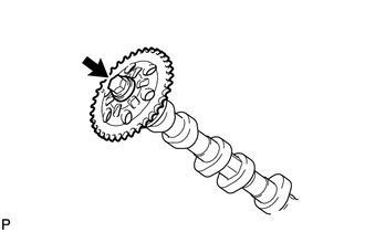
Remove the bolt and camshaft timing sprocket.
Note
Be careful not to damage the No. 2 camshaft and camshaft timing sprocket.
-
-
REMOVE OIL CONTROL VALVE FILTER
-
REMOVE NO. 1 CAMSHAFT BEARING
-
REMOVE NO. 2 CAMSHAFT BEARING