HV RELAY ASSEMBLY REMOVAL
PROCEDURE
-
PRECAUTION
-
CHECK FOR DTC
-
Check for DTCs.
Note
Confirm that P0AA6 (Hybrid Battery Voltage System Isolation Fault) is not output before removing or installing an HV battery module. If this DTC is output, perform troubleshooting for this DTC first.
-
-
REMOVE SERVICE PLUG GRIP
-
DISCONNECT WIRE HARNESS
-
DISCONNECT INVERTER RESERVE TANK ASSEMBLY
-
REMOVE NO. 1 INVERTER RESERVE TANK BRACKET (for 2WD)
-
REMOVE CONNECTOR COVER ASSEMBLY
-
CHECK TERMINAL VOLTAGE
-
INSTALL CONNECTOR COVER ASSEMBLY
-
REMOVE REAR SEAT ASSEMBLY
for Manual Seat: Click here
for Power Seat: Click here
-
REMOVE NO. 2 HYBRID VEHICLE BATTERY SHIELD REINFORCEMENT
-
REMOVE HV BATTERY JUNCTION BLOCK ASSEMBLY
CAUTION:
Wear insulated gloves and use insulated tools.
-
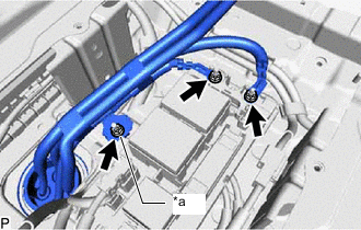
*a Ground Terminal Using an insulated tool, remove the 3 nuts, and disconnect the 2 No. 2 frame wires (high-voltage cables) and ground terminal.
-
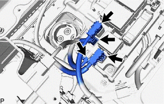
Disconnect the 4 connectors.
Note
Insulate the removed connector with insulating tape.
-
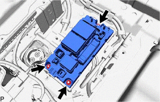
Remove the 3 nuts and hybrid junction block assembly.
Note
If the hybrid battery junction block assembly has been dropped, replace it with a new one.
-