FRAME WIRE REMOVAL
PROCEDURE
-
PRECAUTION
-
REMOVE SERVICE PLUG GRIP
-
REMOVE FUEL TANK SUB-ASSEMBLY
-
w/ Canister Pump Module: Click here
-
w/o Canister Pump Module: Click here
-
-
REMOVE REAR SEAT ASSEMBLY
-
for Manual Seat: Click here
-
for Power Seat: Click here
-
-
REMOVE RADIATOR SUPPORT OPENING COVER
-
DISCONNECT WIRE HARNESS
-
DISCONNECT INVERTER RESERVE TANK ASSEMBLY
-
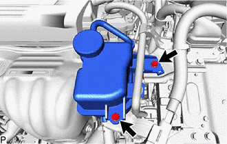
Remove the 2 bolts and disconnect the inverter reserve tank assembly.
-
-
REMOVE NO. 1 INVERTER RESERVE TANK BRACKET (for 2WD)
-
REMOVE CONNECTOR COVER ASSEMBLY
-
CHECK TERMINAL VOLTAGE
-
TEMPORARILY INSTALL CONNECTOR COVER ASSEMBLY
-
DISCONNECT ENGINE WIRE
-
REMOVE NO. 1 ENGINE COVER SUB-ASSEMBLY
-
REMOVE AIR CLEANER CAP SUB-ASSEMBLY
-
REMOVE AIR CLEANER FILTER ELEMENT SUB-ASSEMBLY
-
REMOVE AIR CLEANER CASE SUB-ASSEMBLY
-
REMOVE BATTERY TERMINAL CONNECTOR COVER
-
Remove the battery terminal connector cover.
-
-
REMOVE VOLTAGE INVERTER ASSEMBLY (w/ Voltage Inverter)
-
DISCONNECT POSITIVE AUXILIARY BATTERY TERMINAL
-
REMOVE NO. 2 HYBRID VEHICLE BATTERY SHIELD REINFORCEMENT
CAUTION:
Wear insulated gloves and use insulated tools.
-
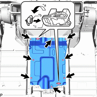
*a Counterclockwise *b Notch *c Protrusion Using the service plug grip, release the 2 battery cover lock strikers.
Tech Tips
Align the protrusion and notch on the service plug grip with the battery cover lock strikers, and turn the button counterclockwise to release the strikers.
-
Using an insulated tool, remove the 8 bolts and No. 2 hybrid vehicle battery shield reinforcement.
-
-
DISCONNECT HV BATTERY JUNCTION BLOCK ASSEMBLY
CAUTION:
Wear insulated gloves and use insulated tools.
Note
Insulate the removed connector with insulating tape.
-
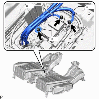
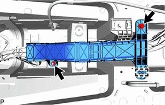
*a No. 2 Frame wire *b Ground Terminal Using an insulated tool, remove the 3 nuts, and disconnect the 2 No. 2 frame wires (high-voltage cables) and ground terminal.
-
-
REMOVE NO. 1 FRONT LOWER FLOOR HEAT INSULATOR
-
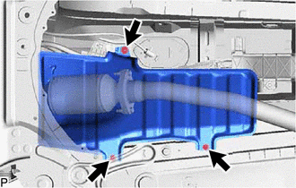
Remove the nut, 2 bolts and No. 1 front lower floor heat insulator.
-
-
REMOVE FRONT EXHAUST PIPE ASSEMBLY
-
REMOVE NO. 13 WIRING HARNESS PROTECTOR
-
Remove the clamp, nut, bolt and No. 13 wiring harness protector.
-
-
REMOVE NO. 14 WIRING HARNESS PROTECTOR
-
*A for AWD *B for 2WD Remove the stud clamp and clamp from the No. 14 wiring harness protector.
-
Remove the nut and No. 14 wiring harness protector.
-
-
REMOVE NO. 2 FRAME WIRE
CAUTION:
Be sure to wear insulated gloves.
Note
Wrap insulation tape around the removed terminals to insulate them.
-
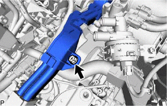
Remove the relay block cover.
-
Remove the nut.
-
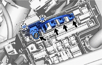
Disconnect the 3 connectors and detach the 2 claws to disconnect the wire harness from the No. 1 relay block.
-
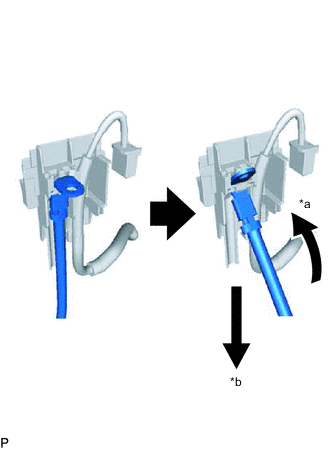
*a Tilt the terminal at an angle *b Pull out the harness Disconnect the terminal from the No. 1 relay block side cover as shown in the illustration.
-
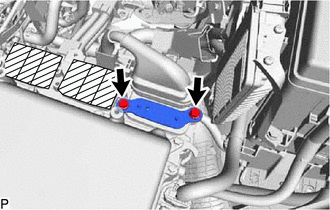
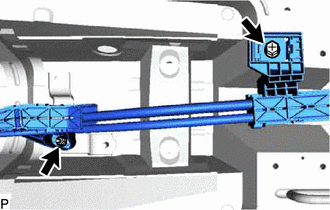
for AWD:
Using an insulated tool, remove the 2 bolts and upper inverter cover (rear motor high-voltage cable side).
Note
-
Make sure to pull the upper inverter cover straight up, as a connector is connected to the bottom of the cover.
-
Do not touch the rubber seal of the upper inverter cover.
-
-
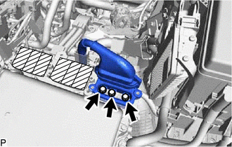
for AWD:
Using an insulated tool, remove the 3 bolts.
-
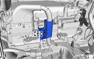
for AWD:
Disconnect the wire harness clamp and the No. 2 frame wire (rear motor high-voltage cable side) from the air cleaner bracket.
Note
-
When disconnecting, do not damage the terminals, connector housing and inverter with converter assembly.
-
Do not touch the connector rubber seal and terminal.
-
Wrap insulation tape around the removed terminals to insulate them.
-
Cover the hole with non-residue tape to prevent entry of foreign matter or water after removing the cable.
-
-
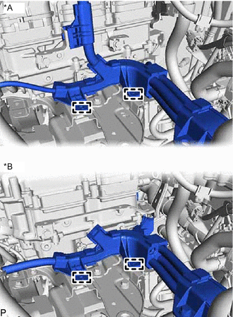
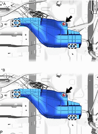
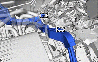
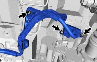
*A for AWD *B for 2WD Detach the 2 clamps.
-
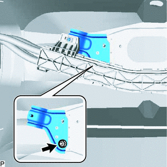
Remove the bolt.
-
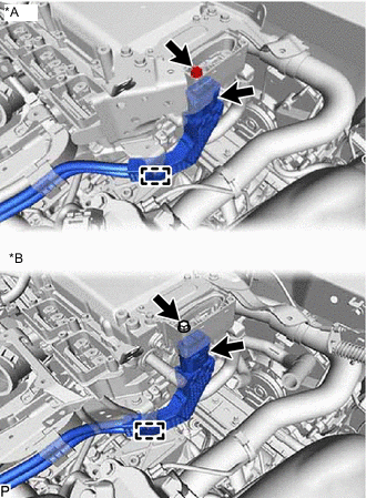
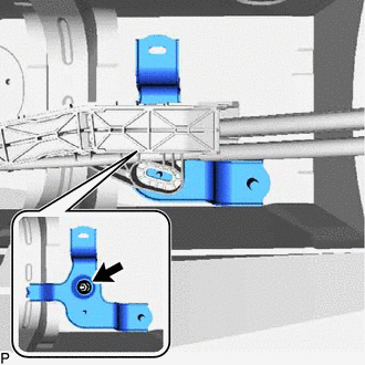
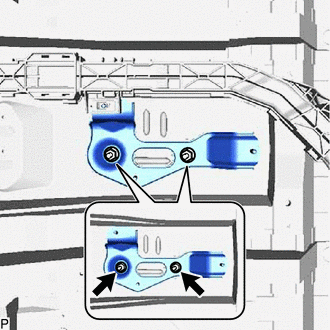
*A for AWD *B for 2WD Remove the bolt.
-
Remove the clamp and disconnect the No. 2 frame wire.
Note
-
When disconnecting, do not damage the terminals, connector housing and inverter with converter assembly.
-
Do not touch the connector rubber seal and terminal.
-
Wrap insulation tape around the removed terminals to insulate them.
-
Cover the hole with non-residue tape to prevent entry of foreign matter or water after removing the cable.
-
-
Detach the 2 clamps.
-
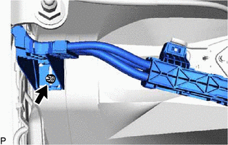
Remove the nut.
-
Remove the nut and bolt.
-
for AWD:
Remove the 3 nuts, and disconnect the No. 2 frame wire (rear motor high-voltage cable side).
-
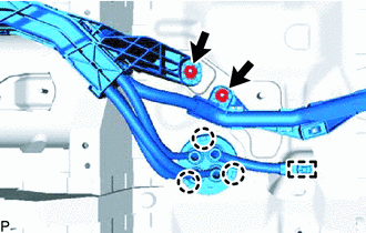
for AWD:
Remove the 2 nuts and clamp and detach the 3 claws and No. 2 frame wire from the floor panel.
-
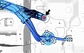
for 2WD:
Remove the nut and clamp and detach the 3 claws and No. 2 frame wire from the floor panel.
-
for AWD:
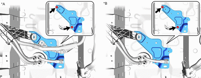
Remove the 4 stud clamps shown in the illustration and the No. 2 frame wire.
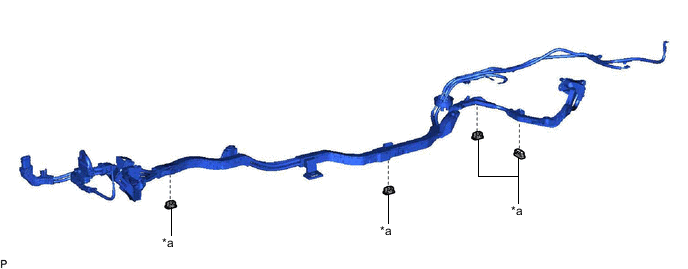
*a Stud Clamp - - Note
Stud clamps are non-reusable parts. When removing them, break and remove the claw.
-
for 2WD:
Remove the 2 stud clamps shown in the illustration and the No. 2 frame wire.
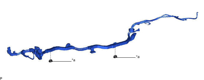
*a Stud Clamp - - Note
Stud clamps are non-reusable parts. When removing them, break and remove the claw.
-
-
REMOVE WIRE HARNESS CLAMP BRACKET
-
Remove the nut and wire harness clamp bracket A.
-
Remove the nut and wire harness clamp bracket B.
-
Remove the 2 nuts and wire harness clamp bracket C.
-
Remove the 2 nuts and wire harness clamp bracket D.
*A for AWD *B for 2WD
-