ЖГУТ ЭЛЕКТРОПРОВОДКИ ТРАНСМИССИИ (если опорный мост двигателя используется) СНЯТИЕ
PROCEDURE
-
PRECAUTION
Note
After turning the engine switch off, waiting time may be required before disconnecting the cable from the negative (-) battery terminal. Therefore, make sure to read the disconnecting the cable from the negative (-) battery terminal notices before proceeding with work.
-
DISCONNECT CABLE FROM NEGATIVE BATTERY TERMINAL
Note
When disconnecting the cable, some systems need to be initialized after the cable is reconnected.
-
REMOVE FRONT WHEELS
-
REMOVE WINDSHIELD WIPER MOTOR AND LINK ASSEMBLY
-
REMOVE OUTER COWL TOP PANEL SUB-ASSEMBLY
-
REMOVE NO. 1 ENGINE UNDER COVER
-
SEPARATE FRONT FENDER LINER LH
-
SEPARATE FRONT FENDER LINER RH
-
REMOVE FRONT FENDER APRON SEAL LH
-
REMOVE FRONT FENDER APRON SEAL RH
-
REMOVE RADIATOR SIDE DEFLECTOR SEAL LH
-
REMOVE RADIATOR SIDE SEAL RH
-
REMOVE COOL AIR INTAKE DUCT SEAL
-
REMOVE V-BANK COVER SUB-ASSEMBLY
-
REMOVE INLET AIR CLEANER ASSEMBLY
-
REMOVE AIR CLEANER ASSEMBLY WITH AIR CLEANER HOSE
-
REMOVE BATTERY
-
DRAIN AUTOMATIC TRANSAXLE FLUID
-
REMOVE THROTTLE BODY WITH MOTOR ASSEMBLY
-
DISCONNECT VENTILATION HOSE
-
DISCONNECT PURGE VALVE (PURGE VSV)
-
REMOVE NO. 2 SURGE TANK STAY
-
REMOVE INTAKE AIR SURGE TANK ASSEMBLY
-
REMOVE AIR SURGE TANK TO INTAKE MANIFOLD GASKET
-
REMOVE WIRE HARNESS CLAMP BRACKET
-
INSTALL ENGINE HANGER
-
INSTALL ENGINE SUPPORT BRIDGE
-
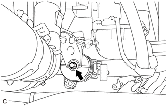
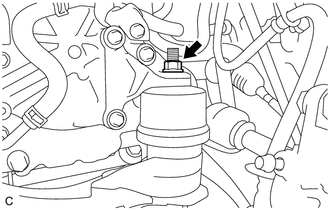
DISCONNECT TRANSMISSION OIL THERMOSTAT
-
Remove the 2 bolts to disconnect the transmission oil thermostat from the front frame assembly.
-
-
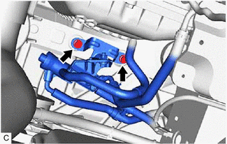
DISCONNECT OUTLET NO. 1 OIL COOLER HOSE
-
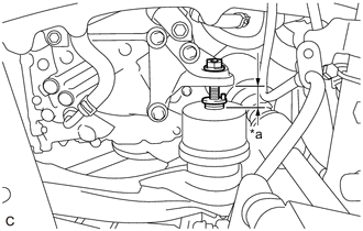
DISCONNECT OIL COOLER UNION SUB-ASSEMBLY
-
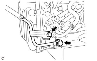
*1 Oil Cooler Union Bolt Remove the bolt to separate the oil cooler union sub-assembly bracket portion from the automatic transaxle case sub-assembly.
-
Remove the oil cooler union bolt, 2 gaskets and disconnect the oil cooler union sub-assembly from the automatic transaxle case sub-assembly.
-
-
REMOVE TRANSMISSION CASE SIDE COVER
-
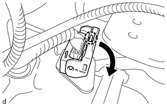
Disconnect the transmission wire connector.
Tech Tips
Disengage the claw, pull down the lever, and then disconnect the transmission wire connector.
-
Loosen the bolt from the front engine mounting insulator.
Note
Do not fully remove the bolt.
-
Loosen the nut from the engine mounting insulator LH.
Note
Do not fully remove the nut.
-
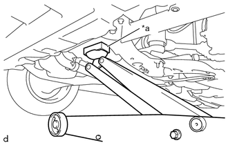
*a Wooden Block Support the automatic transaxle assembly with a jack. Insert a wooden block between the jack and the automatic transaxle assembly to prevent damage.
-
*a 25 to 30 mm Operate the engine support bridge and the jack to raise up the engine and automatic transaxle assembly from 25 to 30 mm (0.984 to 1.181 in.).
Note
-
Do not raise the engine and automatic transaxle more than 30 mm (1.181 in.).
-
When raising the jack, be careful to prevent contact between the transmission wire and the vehicle body.
-
Do not allow the engine assembly and automatic transaxle assembly to interfere with the body.
-
Make sure that the wire harness and hoses are not being pulled.
-
-

Remove the 10 bolts and transmission case side cover from the automatic transaxle case sub-assembly.
-
-
REMOVE TRANSMISSION WIRE
-
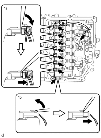
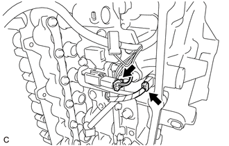
*a Connector A *b Connector B Disengage the clamp to disconnect the transmission wire from the solenoid lock plate.
-
Disconnect the 9 solenoid valve connectors.
Tech Tips
-
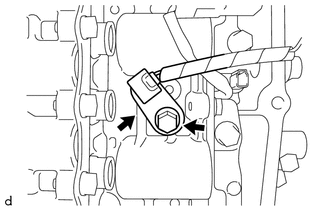
Using a screwdriver, disconnect the solenoid valve connector A using the procedure shown in the illustration.
-
Using a screwdriver, disconnect the solenoid valve connector B using the procedure shown in the illustration.
-
-
Remove the bolt and temperature sensor clamp and disconnect the temperature sensor from the transmission valve body assembly.
-
Disconnect the transmission revolution sensor (NT) connector and transmission revolution sensor (NC) connector.
-
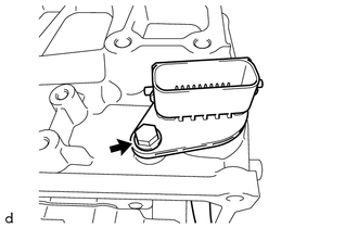
Remove the bolt and transmission wire from the automatic transmission case sub-assembly.
-