REAR BUMPER REASSEMBLY
PROCEDURE
-
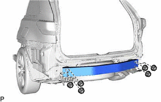
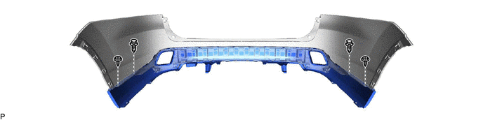
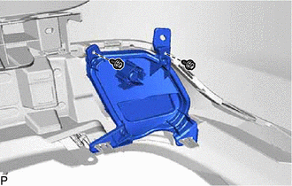
INSTALL NO. 1 REAR BUMPER REINFORCEMENT
-
Install the No. 1 rear bumper reinforcement with the 6 nuts.
- Torque:
- 43 N*m { 438 kgf*cm, 32 ft.*lbf }
-
-
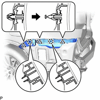
INSTALL REAR BUMPER SIDE SEAL LH
-
Install the rear bumper side seal LH with the 4 clips.
-
-
INSTALL REAR BUMPER SIDE SEAL RH
Tech Tips
Use the same procedure as for the LH side.
-
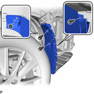
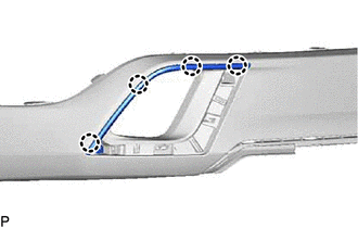
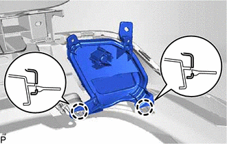
INSTALL REAR BUMPER SIDE SUPPORT LH
-
Engage the 2 claws.
-
Engage the 3 clips as shown in the illustration.
-
Install the rear bumper side support LH with the screw.
-
-
INSTALL REAR BUMPER SIDE SUPPORT RH
Tech Tips
Use the same procedure as for the LH side.
-
INSTALL NO. 2 MOULDING TAPE
Tech Tips
Use the same procedure for the RH side and LH side.
-
Clean the installation surface of the No. 2 moulding tape.
-
Remove any remaining double-sided tape from the rear bumper cover.
Note
-
If there is any foreign matter on the rear bumper cover when the No. 2 moulding tape is installed, adhesion failure may occur.
-
Do not use a screwdriver or other tool to remove the double-sided tape as the rear bumper cover may be damaged, possibly leading to adhesion failure.
-
-
Wipe off any tape adhesive residue with cleaner.
-
-
Install a new No. 2 moulding tape.
CAUTION:
-
Do not touch the heat light, as doing so may cause in burns.
-
Touching heated parts for a long time may result in burns.
Tech Tips
If the temperature of the No. 2 moulding tape or its installation surface on the rear bumper cover is below 15°C (59°F), adhesion failure may occur. Use a heat light to heat the No. 2 moulding tape and its installation surface on the rear bumper cover to the recommended temperature (15 to 40°C (59 to 104°F)).
-
Remove the release paper from the No. 2 moulding tape.
Tech Tips
After removing the release paper, keep the exposed adhesive free from foreign matter.
-
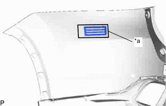
*a Line Install the No. 2 moulding tape to the rear bumper cover as shown in the illustration.
Note
If the No. 2 moulding tape has been removed, it must be replaced with a new one as it may be deformed or the strength of its adhesive may be deteriorated.
Tech Tips
Make sure not to touch the exposed adhesive of the No. 2 moulding tape or the installation surface on the rear bumper cover.
-
Using a squeegee, evenly press the No. 2 moulding tape to the rear bumper cover with a force of 29 N (3 kgf, 6.5lbf) or more.
Tech Tips
-
Make sure that the corners of the No. 2 moulding tape are not damaged or peeling off.
-
After installing the No. 2 moulding tape, leave the rear bumper cover in an area with an ambient temperature of 15°C (59°F) or more for 30 minutes or more to allow the adhesive to set.
-
-
Remove the protector sheet from the No. 2 moulding tape.
-
-
-
INSTALL REAR BUMPER SIDE MOULDING LH (w/ Plated Moulding)
-
Engage the 4 claws to install the rear bumper side moulding LH.
-
-
INSTALL REAR BUMPER SIDE MOULDING RH (w/ Plated Moulding)
Tech Tips
Use the same procedure as for the LH side.
-
INSTALL REAR BUMPER EXTENSION MOULDING LH (w/ Plated Moulding)
-
Engage the 2 claws.
-
Install the rear bumper extension moulding LH with the 2 screws.
-
-
INSTALL REAR BUMPER EXTENSION MOULDING RH (w/ Plated Moulding)
Tech Tips
Use the same procedure as for the LH side.
-
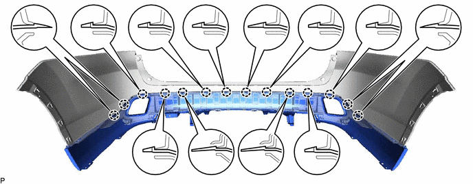
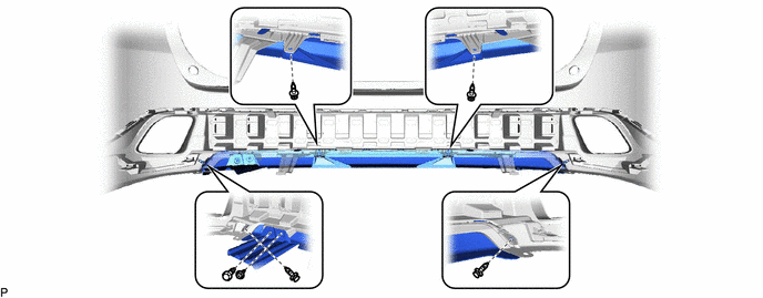
INSTALL LOWER REAR BUMPER COVER
-
Engage the 14 claws.
-
Install the 2 clips.
-
Install the lower rear bumper cover with the 2 screws.
-
-
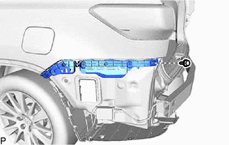
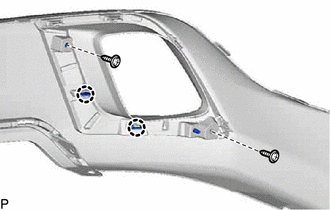
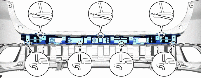
INSTALL REAR BUMPER EXTENSION
-
Engage the 2 guides and 10 claws.
-
Install the 5 clips.
-
Install the rear bumper extension with the screw.
-
-
INSTALL REAR CENTER ULTRASONIC SENSOR RETAINER (w/ TOYOTA Parking Assist-sensor System)
-
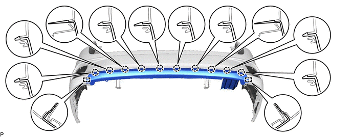
INSTALL REAR BUMPER ENERGY ABSORBER
-
Engage the 7 claws to install the rear bumper energy absorber.
-
-
INSTALL NO. 3 LUGGAGE ROOM WIRE
-
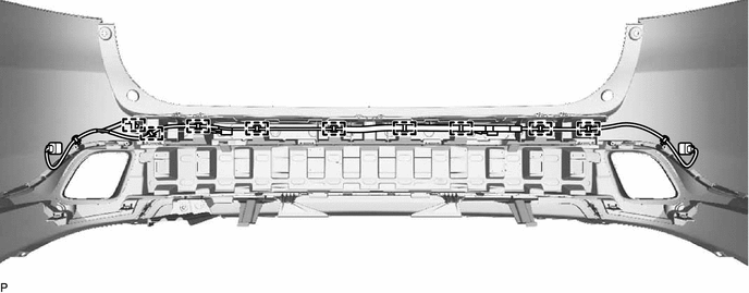
w/o Rear Fog Light with TOYOTA Parking Assist-sensor System:
-
Engage the 9 clamps to install the No. 3 luggage room wire.
-
-
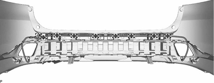
w/ Rear Fog Light without TOYOTA Parking Assist-sensor System:
-
Engage the 9 clamps to install the No. 3 luggage room wire.
-
-
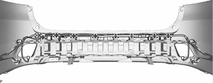
w/ Rear Fog Light and TOYOTA Parking Assist-sensor System:
-
Engage the 9 clamps to install the No. 3 luggage room wire.
-
-
-
INSTALL REAR CORNER ULTRASONIC SENSOR RETAINER (w/ TOYOTA Parking Assist-sensor System)
-
INSTALL NO. 1 ULTRASONIC SENSOR (w/ TOYOTA Parking Assist-sensor System)
for Corner Sensor:
-
INSTALL NO. 1 ULTRASONIC SENSOR (w/ TOYOTA Parking Assist-sensor System)
for Back Sensor:
-
INSTALL REFLEX REFLECTOR ASSEMBLY LH (w/o Rear Fog Light)
-
Engage the 2 claws.
-
Install the reflex reflector assembly LH with the 2 screws.
-
Engage the clamp.
-
-
INSTALL REFLEX REFLECTOR ASSEMBLY RH (w/o Rear Fog Light)
Tech Tips
Use the same procedure as for the LH side.
-
INSTALL REAR FOG LIGHT ASSEMBLY LH (w/ Rear Fog Light)
-
INSTALL REAR FOG LIGHT ASSEMBLY RH (w/ Rear Fog Light)
Tech Tips
Use the same procedure as for the LH side.