FRONT BUMPER REMOVAL
CAUTION / NOTICE / HINT
Tech Tips
When the front bumper is damaged or deformed due to an accident or contact with other objects, etc., or the bumper installation area on the body is repaired, it is necessary to perform millimeter wave radar sensor adjustment.
PROCEDURE
-
REMOVE RADIATOR GRILLE ASSEMBLY
-
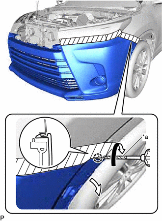
DISCONNECT FRONT FENDER WHEEL OPENING MOULDING SUB-ASSEMBLY LH
-
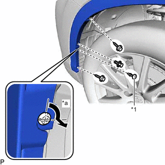
*1 Pin Hold Clip *a 90° Using a screwdriver, turn the pin 90 degrees and remove the pin hold clip.
-
Remove the 2 screws.
-
Remove the clip.
-
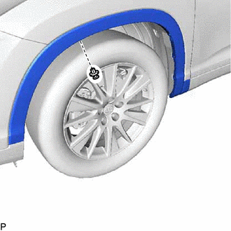
Remove the clip.
-
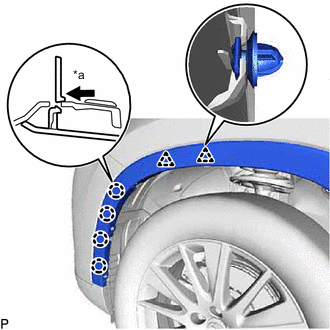
*a Push Pull back the edge of the front fender liner LH and disengage the 4 claws by pushing the area indicated by the arrow in the illustration with a finger.
Note
-
Do not apply excessive force when pulling back the front fender liner LH.
-
To avoid damaging the claws, do not forcibly pull the front fender wheel opening moulding sub-assembly LH.
-
-
Disengage the 2 clips and disconnect the front fender wheel opening moulding sub-assembly LH.
-
-
DISCONNECT FRONT FENDER WHEEL OPENING MOULDING SUB-ASSEMBLY RH
Tech Tips
Use the same procedure as for the LH side.
-
REMOVE FRONT BUMPER ASSEMBLY
-
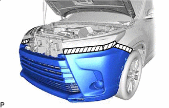

Protective Tape Apply protective tape around the front bumper assembly as shown in the illustration.
-
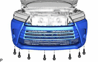
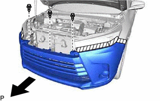
Remove the 8 screws.
-
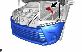
*a Protective Tape Using a screwdriver with its tip wrapped with protective tape, disengage the claw as shown in the illustration.
Tech Tips
Use the same procedure for the RH side and LH side.
-
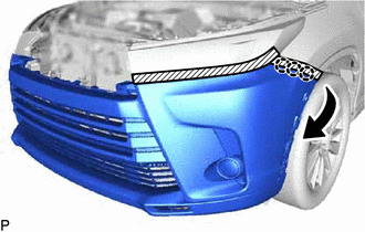
Disengage the 3 claws as shown in the illustration.
Tech Tips
Use the same procedure for the RH side and LH side.
-
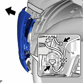
*A w/ TOYOTA Parking Assist-sensor System (for 6 Sensor Type) Pull back the side of the front bumper assembly, disengage each clamp and disconnect each connector.
Note
Do not apply excessive force when pulling back the front bumper assembly.
Tech Tips
Use the same procedure for the RH side and LH side.
-
w/ Panoramic View Monitor System:
-
Disconnect the connector.
-
-
Remove the 3 clips and front bumper assembly as shown in the illustration.
-