HEADLIGHT ASSEMBLY(for LED Headlight) REASSEMBLY
PROCEDURE
-
INSTALL HEADLIGHT LEVELING MOTOR
-
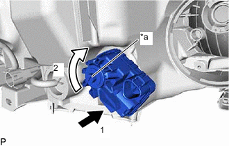
*a Aiming Screw Insert the headlight leveling motor in the direction indicated by the arrow (1) shown in the illustration.
-
Turn the aiming screw of the headlight leveling motor in the direction indicated by the arrow (2) shown in the illustration to engage the shaft.
Tech Tips
Turn the aiming screw the same number of times as it was turned during removal.
-
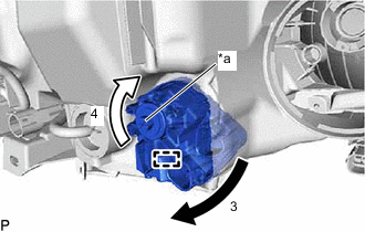
*a Aiming Screw Turn the headlight leveling motor in the direction indicated by the arrow (3) shown in the illustration and engage the pin to install the headlight leveling motor to the headlight unit.
-
Turn the aiming screw of the headlight leveling motor in the direction indicated by the arrow (4) shown in the illustration.
Tech Tips
Turn the aiming screw the same number of times as it was turned during removal.
-
-
INSTALL HEADLIGHT GASKET
-
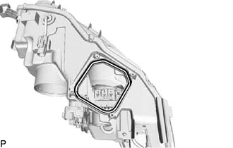
Install a new headlight gasket.
-
-
INSTALL LIGHT CONTROL ECU
-
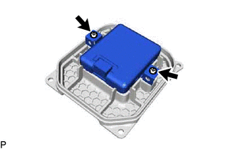
Install the light control ECU with the 2 screws.
-
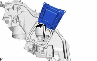
Connect the connector.
-
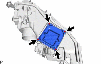
Install the light control ECU with the No. 1 headlight back cover with the 4 screws.
-
-
INSTALL CLEARANCE LIGHT BULB
-
Install the clearance light bulb to the socket.
-
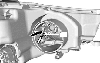
*a Socket Connect the socket with the clearance light bulb as shown in the illustration.
-
-
INSTALL FRONT TURN SIGNAL LIGHT SOCKET
-
Connect the connector to install the front turn signal light socket to the headlight cord.
-
-
INSTALL FRONT TURN SIGNAL LIGHT BULB
-
Install the front turn signal light bulb to the headlight cord.
-
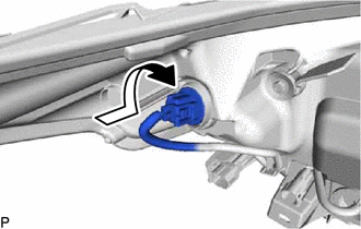
Turn the headlight cord with the front turn signal light bulb as shown in the illustration to connect them as a unit.
-
-
INSTALL NO. 1 HEADLIGHT BULB
-
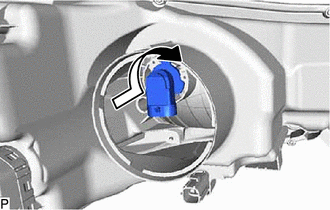
Turn the No. 1 headlight bulb as shown in the illustration to install it.
Note
Do not touch the bulb glass.
-
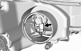
Connect the connector.
-
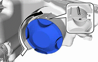
*a Lock Mark Turn the back cover assembly as shown in the illustration until the lock marks are aligned to install it.
-