LIGHTING SYSTEM Door Mirror Foot Light Circuit
DESCRIPTION
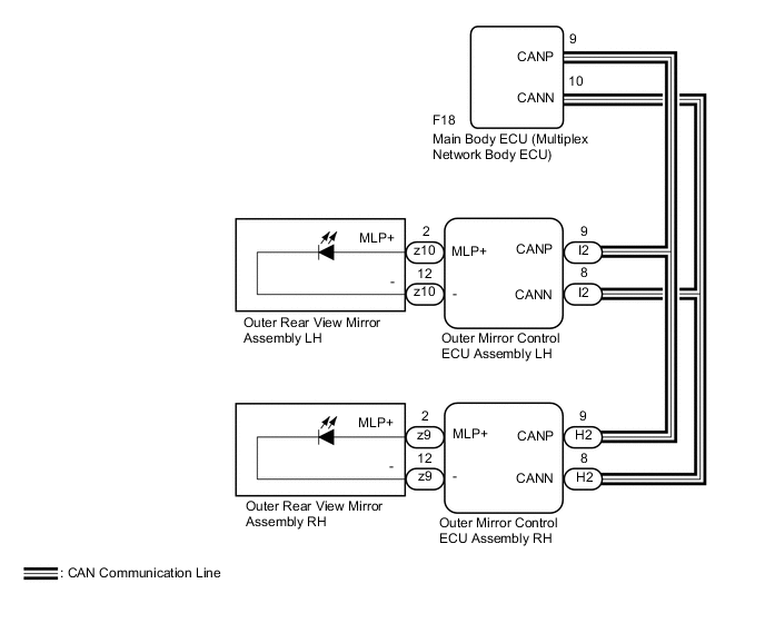
The outer mirror control ECU assembly receives signals from the main body ECU (multiplex network body ECU) to control the door mirror foot lights.
WIRING DIAGRAM
CAUTION / NOTICE / HINT
Note
-
If the main body ECU (multiplex network body ECU) is replaced, refer to Service Bulletin.*
-
*: w/ Smart Entry and Start System
-
As the door control battery is installed between the vehicle battery and main body ECU (multiplex network body ECU), first perform the inspections in On-Vehicle Inspection to confirm that there are no malfunctions in the power source circuit for the main body ECU (multiplex network body ECU) before performing this troubleshooting procedure.*
-
*: for LHD
PROCEDURE
-
PERFORM ACTIVE TEST USING GTS
-
Connect the GTS to the DLC3.
-
Turn the ignition switch to ON.
-
Turn the GTS on.
-
Enter the following menus: Body Electrical / Mirror L or Mirror R / Active Test.
-
Check that the door mirror foot lights illuminate.
Body Electrical > Mirror L > Active TestTester Display Measurement Item Control Range Diagnostic Note Foot Light Door mirror foot light LH ON/OFF -
Body Electrical > Mirror R > Active TestTester Display Measurement Item Control Range Diagnostic Note Foot Light Door mirror foot light RH ON/OFF -
Body Electrical > Mirror L > Active TestTester Display Foot Light
Body Electrical > Mirror R > Active TestTester Display Foot Light OK Door mirror foot lights illuminate. Result Result Proceed to OK A NG (Door mirror foot light LH does not illuminate) B NG (Door mirror foot light RH does not illuminate) C
A 
PROCEED TO NEXT SUSPECTED AREA SHOWN IN PROBLEM SYMPTOMS TABLE Click here
C 
INSPECT OUTER REAR VIEW MIRROR ASSEMBLY RH Click here
B 
-
-
INSPECT OUTER REAR VIEW MIRROR ASSEMBLY LH
-
Remove the outer rear view mirror assembly LH.
-
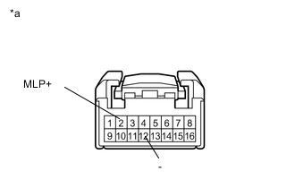
*a Component without harness connected
(Outer Rear View Mirror Assembly LH)
Connect a positive (+) lead from the battery to terminal 2 (MLP+) and a negative (-) lead to terminal 12 (-).
-
Check that the door mirror foot light LH illuminates.
OK Door mirror foot light illuminates. Result Proceed to OK NG
OK
REPLACE OUTER MIRROR CONTROL ECU ASSEMBLY LH Click here
NG
REPLACE OUTER REAR VIEW MIRROR ASSEMBLY LH Click here
-
-
INSPECT OUTER REAR VIEW MIRROR ASSEMBLY RH
-
Remove the outer rear view mirror assembly RH.
-
*a Component without harness connected
(Outer Rear View Mirror Assembly RH)
Connect a positive (+) lead from the battery to terminal 2 (MLP+) and a negative (-) lead to terminal 12 (-).
-
Check that the door mirror foot light RH illuminates.
OK Door mirror foot light illuminates. Result Proceed to OK NG
OK
REPLACE OUTER MIRROR CONTROL ECU ASSEMBLY RH Click here
NG
REPLACE OUTER REAR VIEW MIRROR ASSEMBLY RH Click here
-