LIGHTING SYSTEM TERMINALS OF ECU
-
CHECK INSTRUMENT PANEL JUNCTION BLOCK ASSEMBLY AND MAIN BODY ECU (MULTIPLEX NETWORK BODY ECU)
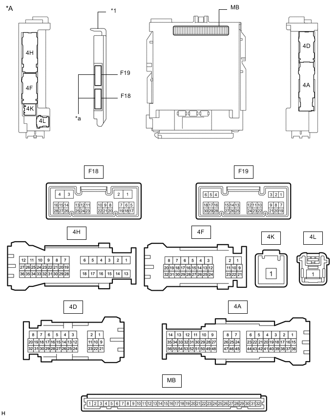
*A Main Body ECU (Multiplex Network Body ECU) with 2 Connectors - - *1 Main Body ECU (Multiplex Network Body ECU) - - *a 2 Connectors - - 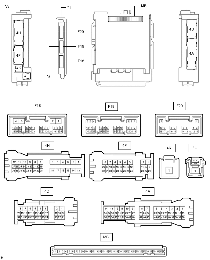
*A Main Body ECU (Multiplex Network Body ECU) with 3 Connectors - - *1 Main Body ECU (Multiplex Network Body ECU) - - *a 3 Connectors - -
-
Disconnect the instrument panel junction block assembly and main body ECU (multiplex network body ECU) connectors.
-
Measure the voltage on the wire harness side connector according to the value(s) in the table below.
Terminal No. (Symbol) Wiring Color Terminal Description Condition Specified Condition 4F-32 - Body ground BE - Body ground Battery power supply Always 11 to 14 V 4K-1 - Body ground B - Body ground Battery power supply Always 11 to 14 V If the result is not as specified, there may be a malfunction in the wire harness.
-
Measure the resistance on the wire harness side connector according to the value(s) in the table below.
Terminal No. (Symbol) Wiring Color Terminal Description Condition Specified Condition 4D-11 - Body ground LA - Body ground Ground Always Below 1 Ω If the result is not as specified, there may be a malfunction in the wire harness.
-
Reconnect the instrument panel junction block assembly and main body ECU (multiplex network body ECU) connectors.
-
Measure the voltage and check for pulses according to the value(s) in the table below.
Terminal No. (Symbol) Wiring Color Terminal Description Condition Specified Condition 4A-48 - Body ground B - Body ground Battery power supply Always 11 to 14 V 4D-23 - Body ground BE - Body ground Battery power supply Always 11 to 14 V 4F-4 - Body ground LG - Body ground Clearance lights drive output Light control switch in tail or head position 11 to 14 V Light control switch off Below 1 V 4H-17 - Body ground LA-Y - Body ground Taillights (rear combination light assembly) drive output Light control switch in tail or head position 11 to 14 V Light control switch off Below 1 V 4H-16 - Body ground LA-Y - Body ground Taillights (rear light assembly), license plate lights and rear fog lights*2 drive output Light control switch in tail or head position 11 to 14 V Light control switch off Below 1 V 4H-26 - Body ground*1 LG - Body ground Rear fog light relay power supply output Light control switch in tail or head position 11 to 14 V Light control switch off Below 1 V 4F-27 - Body ground R - Body ground Headlight relay drive output Light control switch in head position Below 1 V Light control switch not in head position 11 to 14 V 4F-26 - Body ground L - Body ground Daytime running light system drive output Daytime running light system operating Below 1 V Daytime running light system not operating 11 to 14 V 4F-25 - Body ground GR - Body ground Front fog light drive output Light control switch in tail or head position, fog light switch in front position Below 1 V Light control switch in tail or head position, fog light switch off 11 to 14 V F19-1 (DIM) - Body ground BE - Body ground High beam headlight drive output Dimmer switch in high or high flash position Below 1 V Dimmer switch in low position 11 to 14 V 4F-28 - Body ground G - Body ground Parking brake switch input Ignition switch ON, parking brake switch on Below 1 V Ignition switch ON, parking brake switch off 11 to 14 V F19-24 (HU) - Body ground Y - Body ground Dimmer switch high position signal input Dimmer switch in high position Below 1 V Dimmer switch not in high position 11 to 14 V or Pulse generation F19-10 (HF) - Body ground SB - Body ground Dimmer switch high flash position signal input Dimmer switch in high flash position Below 1 V Dimmer switch not in high flash position 11 to 14 V or Pulse generation F19-19 (CLTB) - F19-21 (CLTE) L - G Automatic light control sensor power supply output Ignition switch off, dimmer switch off, 2 minutes after all doors closed Below 1 V Ignition switch ON 11 to 14 V F19-20 (CLTS) - Body ground R - Body ground Automatic light control sensor signal input Ignition switch off, dimmer switch off, 2 minutes after all doors closed Below 1 V Ignition switch ON Communication waveform generation
(See waveform 1)
F19-23 (RFOG) - Body ground*1 LG - Body ground Fog light switch rear position input Fog light switch in rear position Below 1 V Ignition switch off, fog light switch off 11 to 14 V or Pulse generation F19-26 (FFOG) - Body ground GR - Body ground Fog light switch front position input Fog light switch in front position Below 1 V Ignition switch off, fog light switch off 11 to 14 V or Pulse generation F19-8 (A) - Body ground B - Body ground Light control switch AUTO position signal input Light control switch in AUTO position Below 1 V Ignition switch off, light control switch not in AUTO position 11 to 14 V or Pulse generation F19-12 (HEAD) - Body ground W - Body ground Light control switch head position input Light control switch in head position Below 1 V Ignition switch off, light control switch not in head position 11 to 14 V or Pulse generation F19-22 (TAIL) - Body ground LG - Body ground Light control switch tail position signal input Light control switch in tail or head position Below 1 V Ignition switch off, light control switch not in tail or head position 11 to 14 V or Pulse generation F19-3 (RLEW) - Body ground*2 V - Body ground Light control ECU RH signal input Ignition switch ON, light control switch off 11 to 14 V Ignition switch ON, light control switch in head position Pulse generation F19-16 (LLEW) - Body ground*2 P - Body ground Light control ECU LH signal input Ignition switch ON, light control switch off 11 to 14 V Ignition switch ON, light control switch in head position Pulse generation
-
*1: w/ Rear Fog Light
-
*2: for LED Headlight
If the result is not as specified, the main body ECU (multiplex network body ECU) or instrument panel junction block assembly may be malfunctioning.
-
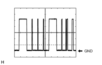
Waveform 1
Item Content Tool setting 2 V/DIV., 10 ms./DIV. Vehicle condition Ignition switch ON Tech Tips
The communication waveform changes according to the surrounding brightness.
-
-
-
CHECK COMBINATION METER ASSEMBLY
-
CHECK OUTER MIRROR CONTROL ECU ASSEMBLY LH (w/ Door Mirror Foot Light)
-
CHECK OUTER MIRROR CONTROL ECU ASSEMBLY RH (w/ Door Mirror Foot Light)