LIGHTING SYSTEM Headlight Dimmer Switch Circuit
DESCRIPTION
The main body ECU (multiplex network body ECU) receives the following switch information:
-
Light control switch in off, tail, head or AUTO position.
-
Dimmer switch in high, low or high flash (pass) position.
-
Fog light switch in front, rear or off position.
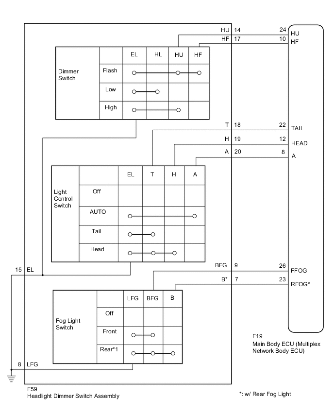
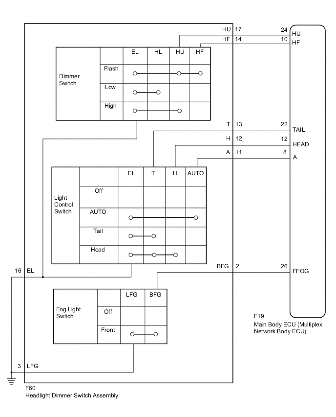
WIRING DIAGRAM
-
for LHD
-
for RHD
CAUTION / NOTICE / HINT
Note
-
If the main body ECU (multiplex network body ECU) is replaced, refer to Service Bulletin.*
-
*: w/ Smart Entry and Start System
-
As the door control battery is installed between the vehicle battery and main body ECU (multiplex network body ECU), first perform the inspections in On-Vehicle Inspection to confirm that there are no malfunctions in the power source circuit for the main body ECU (multiplex network body ECU) before performing this troubleshooting procedure.*
-
*: for LHD
PROCEDURE
-
READ VALUE USING GTS
-
Connect the GTS to the DLC3.
-
Turn the ignition switch to ON.
-
Turn the GTS on.
-
Enter the following menus: Body Electrical / Main Body / Data List.
-
Read the display on the GTS.
Body Electrical > Main Body > Data ListTester Display Measurement Item Range Normal Condition Diagnostic Note Dimmer SW Dimmer switch high position signal ON or OFF ON: Dimmer switch in high or high flash position
OFF: Dimmer switch in low position
- Passing Light SW Dimmer switch high flash position (pass) signal ON or OFF ON: Dimmer switch in high flash position
OFF: Dimmer switch not in high flash position
- Rear Fog Light SW Fog light switch rear position ON or OFF ON: Fog light switch in rear position
OFF: Fog light switch off
* Front Fog Light SW Fog light switch front position signal ON or OFF ON: Fog light switch in front position
OFF: Fog light switch off
- Auto Light SW Light control switch AUTO position signal ON or OFF ON: Light control switch in AUTO position
OFF: Light control switch not in AUTO position
- Head Light SW (Head) Light control switch head position signal ON or OFF ON: Light control switch in head position
OFF: Light control switch not in head position
- Head Light SW (Tail) Light control switch tail position signal ON or OFF ON: Light control switch in tail or head position
OFF: Light control switch in neither tail nor head position
-
-
*: w/ Rear Fog Light
Body Electrical > Main Body > Data ListTester Display Dimmer SW Passing Light SW Rear Fog Light SW Front Fog Light SW Auto Light SW Head Light SW (Head) Head Light SW (Tail) OK Normal conditions listed above are displayed. Result Proceed to OK NG -
OK 
PROCEED TO NEXT SUSPECTED AREA SHOWN IN PROBLEM SYMPTOMS TABLE Click here
NG 
-
-
INSPECT HEADLIGHT DIMMER SWITCH ASSEMBLY
Tech Tips
Inspect the items that did not change as a result of monitoring the Data List.
-
Remove the headlight dimmer switch assembly.
-
for LHD:
-
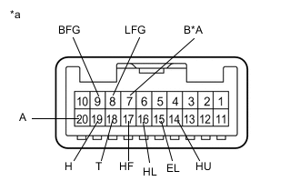
*A w/ Rear Fog Light *a Component without harness connected
(Headlight Dimmer Switch Assembly)
Measure the resistance according to the value(s) in the table below.
Standard Resistance Light Control Switch Tester Connection Condition Specified Condition 18 (T) - 15 (EL) Light control switch off 10 kΩ or higher 19 (H) - 15 (EL) 10 kΩ or higher 20 (A) - 15 (EL) 10 kΩ or higher 19 (H) - 18 (T) 10 kΩ or higher 20 (A) - 18 (T) 10 kΩ or higher 19 (H) - 20 (A) 10 kΩ or higher 18 (T) - 15 (EL) Light control switch in tail position Below 1 Ω 18 (T) - 15 (EL) Light control switch in head position Below 1 Ω 19 (H) - 15 (EL) Below 1 Ω 18 (T) - 19 (H) Below 1 Ω 20 (A) - 15 (EL) Light control switch in AUTO position Below 1 Ω Dimmer Switch Tester Connection Condition Specified Condition 16 (HL) - 15 (EL) Dimmer switch in low position Below 1 Ω 14 (HU) - 15 (EL) Dimmer switch in high position Below 1 Ω 14 (HU) - 15 (EL) Dimmer switch in high flash position Below 1 Ω 17 (HF) - 15 (EL) Below 1 Ω 14 (HU) - 17 (HF) Below 1 Ω Fog Light Switch Tester Connection Condition Specified Condition 9 (BFG) - 8 (LFG) Fog light switch off 10 kΩ or higher 7 (B) - 8 (LFG)* 10 kΩ or higher 7 (B) - 9 (BFG) 10 kΩ or higher 9 (BFG) - 8 (LFG) Fog light switch in front position Below 1 Ω 7 (B) - 8 (LFG)* Fog light switch in rear position Below 1 Ω 9 (BFG) - 8 (LFG)* Below 1 Ω 9 (BFG) - 7 (B)* Below 1 Ω
-
*: w/ Rear Fog Light
-
-
-
for RHD:
-
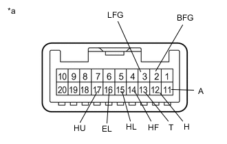
*a Component without harness connected
(Headlight Dimmer Switch Assembly)
Measure the resistance according to the value(s) in the table below.
Standard Resistance Light Control Switch Tester Connection Condition Specified Condition 13 (T) - 16 (EL) Light control switch off 10 kΩ or higher 12 (H) - 16 (EL) 10 kΩ or higher 11 (A) - 16 (EL) 10 kΩ or higher 11 (A) - 12 (H) 10 kΩ or higher 11 (A) - 13 (T) 10 kΩ or higher 12 (H) - 13 (T) 10 kΩ or higher 13 (T) - 16 (EL) Light control switch in tail position Below 1 Ω 13 (T) - 16 (EL) Light control switch in head position Below 1 Ω 12 (H) - 16 (EL) Below 1 Ω 12 (H) - 13 (T) Below 1 Ω 11 (A) - 16 (EL) Light control switch in AUTO position Below 1 Ω Dimmer Switch Tester Connection Condition Specified Condition 15 (HL) - 16 (EL) Dimmer switch in low position Below 1 Ω 17 (HU) - 16 (EL) Dimmer switch in high position Below 1 Ω 17 (HU) - 16 (EL) Dimmer switch in high flash position Below 1 Ω 14 (HF) - 16 (EL) Below 1 Ω 14 (HF) - 17 (HU) Below 1 Ω Fog Light Switch Tester Connection Condition Specified Condition 2 (BFG) - 3 (LFG) Fog light switch off 10 kΩ or higher 2 (BFG) - 3 (LFG) Fog light switch in front position Below 1 Ω
Result Proceed to OK NG -
NG
REPLACE HEADLIGHT DIMMER SWITCH ASSEMBLY Click here
OK
-
-
CHECK HARNESS AND CONNECTOR (HEADLIGHT DIMMER SWITCH ASSEMBLY - MAIN BODY ECU (MULTIPLEX NETWORK BODY ECU))
-
Disconnect the F19 main body ECU (multiplex network body ECU) connector.
-
for LHD:
-
Measure the resistance according to the value(s) in the table below.
Standard Resistance Tester Connection Condition Specified Condition F59-14 (HU) - F19-24 (HU) Always Below 1 Ω F59-17 (HF) - F19-10 (HF) Always Below 1 Ω F59-18 (T) - F19-22 (TAIL) Always Below 1 Ω F59-19 (H) - F19-12 (HEAD) Always Below 1 Ω F59-20 (A) - F19-8 (A) Always Below 1 Ω F59-9 (BFG) - F19-26 (FFOG) Always Below 1 Ω F59-7 (B) - F19-23 (RFOG)* Always Below 1 Ω F59-14 (HU) - Body ground Always 10 kΩ or higher F59-17 (HF) - Body ground Always 10 kΩ or higher F59-18 (T) - Body ground Always 10 kΩ or higher F59-19 (H) - Body ground Always 10 kΩ or higher F59-20 (A) - Body ground Always 10 kΩ or higher F59-9 (BFG) - Body ground Always 10 kΩ or higher F59-7 (B) - Body ground*1 Always 10 kΩ or higher F59-15 (EL) - Body ground Always Below 1 Ω F59-8 (LFG) - Body ground Always Below 1 Ω
-
*: w/ Rear Fog Light
-
-
-
for RHD:
-
Measure the resistance according to the value(s) in the table below.
Standard Resistance Tester Connection Condition Specified Condition F60-17 (HU) - F19-24 (HU) Always Below 1 Ω F60-14 (HF) - F19-10 (HF) Always Below 1 Ω F60-13 (T) - F19-22 (TAIL) Always Below 1 Ω F60-12 (H) - F19-12 (HEAD) Always Below 1 Ω F60-11 (A) - F19-8 (A) Always Below 1 Ω F60-2 (BFG) - F19-26 (FFOG) Always Below 1 Ω F60-17 (HU) - Body ground Always 10 kΩ or higher F60-14 (HF) - Body ground Always 10 kΩ or higher F60-13 (T) - Body ground Always 10 kΩ or higher F60-12 (H) - Body ground Always 10 kΩ or higher F60-11 (A) - Body ground Always 10 kΩ or higher F60-2 (BFG) - Body ground Always 10 kΩ or higher F60-16 (EL) - Body ground Always Below 1 Ω F60-3 (LFG) - Body ground Always Below 1 Ω
Result Proceed to OK NG -
OK
REPLACE MAIN BODY ECU (MULTIPLEX NETWORK BODY ECU) Click here
NG
REPAIR OR REPLACE HARNESS OR CONNECTOR
-