LIGHTING SYSTEM Turn Signal Switch Circuit
DESCRIPTION
The combination meter assembly receives the turn signal switch information and controls the turn signal lights.
WIRING DIAGRAM
-
for LHD

*1 Turn Signal Switch *2 Off *3 Combination Meter Assembly *4 Headlight Dimmer Switch Assembly -
for RHD
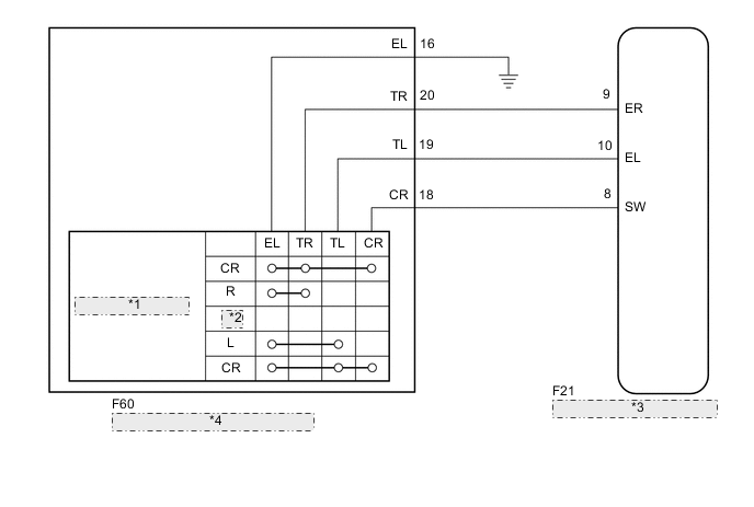
*1 Turn Signal Switch *2 Off *3 Combination Meter Assembly *4 Headlight Dimmer Switch Assembly
PROCEDURE
-
READ VALUE USING GTS
-
Connect the GTS to the DLC3.
-
Turn the ignition switch to ON.
-
Turn the GTS on.
-
Enter the following menus: Body Electrical / Combination Meter / Data List.
-
Read the display on the GTS.
Body Electrical > Combination Meter > Data ListTester Display Measurement Item Range Normal Condition Diagnostic Note Turn Signal Switch (Right) Turn signal switch (right) signal ON or OFF ON: Turn signal switch (right) on
OFF: Turn signal switch (right) off
- Turn Signal Switch (Left) Turn signal switch (left) signal ON or OFF ON: Turn signal switch (left) on
OFF: Turn signal switch (left) off
- Turn Switch Signal (Full Turn) Turn signal switch (full turn) signal ON or OFF ON: Turn signal switch (left or right) on
OFF: Turn signal switch (left and right) off
-
Body Electrical > Combination Meter > Data ListTester Display Turn Signal Switch (Right) Turn Signal Switch (Left) Turn Switch Signal (Full Turn) OK Normal conditions listed above are displayed. Result Proceed to OK NG
OK 
PROCEED TO NEXT SUSPECTED AREA SHOWN IN PROBLEM SYMPTOMS TABLE Click here
NG 
-
-
INSPECT HEADLIGHT DIMMER SWITCH ASSEMBLY
-
Remove the headlight dimmer switch assembly.
-
for LHD:
-
*a Component without harness connected
(Headlight Dimmer Switch Assembly)
Measure the resistance according to the value(s) in the table below.
Standard Resistance Tester Connection Condition Specified Condition 12 (TR) - 15 (EL) Turn signal switch in neutral position 10 kΩ or higher 11 (TL) - 15 (EL) 10 kΩ or higher 13 (CR) - 15 (EL) 10 kΩ or higher 12 (TR) - 11 (TL) 10 kΩ or higher 13 (CR) - 11 (TL) 10 kΩ or higher 12 (TR) - 13 (CR) 10 kΩ or higher 12 (TR) - 15 (EL) Turn signal switch in right turn position Below 1 Ω 12 (TR) - 15 (EL) Turn signal switch in full right turn position Below 1 Ω 13 (CR) - 15 (EL) Below 1 Ω 12 (TR) - 13 (CR) Below 1 Ω 11 (TL) - 15 (EL) Turn signal switch in left turn position Below 1 Ω 11 (TL) - 15 (EL) Turn signal switch in full left turn position Below 1 Ω 13 (CR) - 15 (EL) Below 1 Ω 11 (TL) - 13 (CR) Below 1 Ω
-
-
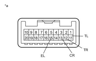
for RHD:
-
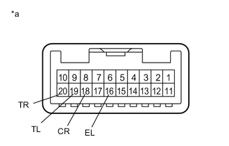
*a Component without harness connected
(Headlight Dimmer Switch Assembly)
Measure the resistance according to the value(s) in the table below.
Standard Resistance Tester Connection Condition Specified Condition 20 (TR) - 16 (EL) Turn signal switch in neutral position 10 kΩ or higher 19 (TL) - 16 (EL) 10 kΩ or higher 18 (CR) - 16 (EL) 10 kΩ or higher 19 (TL) - 20 (TR) 10 kΩ or higher 19 (TL) - 18 (CR) 10 kΩ or higher 18 (CR) - 20 (TR) 10 kΩ or higher 20 (TR) - 16 (EL) Turn signal switch in right turn position Below 1 Ω 18 (CR) - 16 (EL) Turn signal switch in full right turn position Below 1 Ω 20 (TR) - 16 (EL) Below 1 Ω 18 (CR) - 20 (TR) Below 1 Ω 19 (TL) - 16 (EL) Turn signal switch in left turn position Below 1 Ω 18 (CR) - 16 (EL) Turn signal switch in full left turn position Below 1 Ω 19 (TL) - 16 (EL) Below 1 Ω 18 (CR) - 19 (TL) Below 1 Ω
Result Proceed to OK NG -
NG
REPLACE HEADLIGHT DIMMER SWITCH ASSEMBLY Click here
OK
-
-
CHECK HARNESS AND CONNECTOR (HEADLIGHT DIMMER SWITCH ASSEMBLY - COMBINATION METER ASSEMBLY OR BODY GROUND)
-
Disconnect the F21 combination meter assembly connector.
-
for LHD:
-
Measure the resistance according to the value(s) in the table below.
Standard Resistance Tester Connection Condition Specified Condition F59-12 (TR) - F21-9 (ER) Always Below 1 Ω F59-11 (TL) - F21-10 (EL) Always Below 1 Ω F59-13 (CR) - F21-8 (SW) Always Below 1 Ω F59-12 (TR) - Body ground Always 10 kΩ or higher F59-11 (TL) - Body ground Always 10 kΩ or higher F59-13 (CR) - Body ground Always 10 kΩ or higher F59-15 (EL) - Body ground Always Below 1 Ω
-
-
for RHD:
-
Measure the resistance according to the value(s) in the table below.
Standard Resistance Tester Connection Condition Specified Condition F60-20 (TR) - F21-9 (ER) Always Below 1 Ω F60-19 (TL) - F21-10 (EL) Always Below 1 Ω F60-18 (CR) - F21-8 (SW) Always Below 1 Ω F60-20 (TR) - Body ground Always 10 kΩ or higher F60-19 (TL) - Body ground Always 10 kΩ or higher F60-18 (CR) - Body ground Always 10 kΩ or higher F60-16 (EL) - Body ground Always Below 1 Ω
Result Proceed to OK NG -
OK
PROCEED TO NEXT SUSPECTED AREA SHOWN IN PROBLEM SYMPTOMS TABLE Click here
NG
REPAIR OR REPLACE HARNESS OR CONNECTOR
-