LIGHTING SYSTEM, Diagnostic DTC:B2430, B2431
| DTC Code | DTC Name |
|---|---|
| B2430 | LED Headlight LH Circuit Malfunction |
| B2431 | LED Headlight RH Circuit Malfunction |
DESCRIPTION
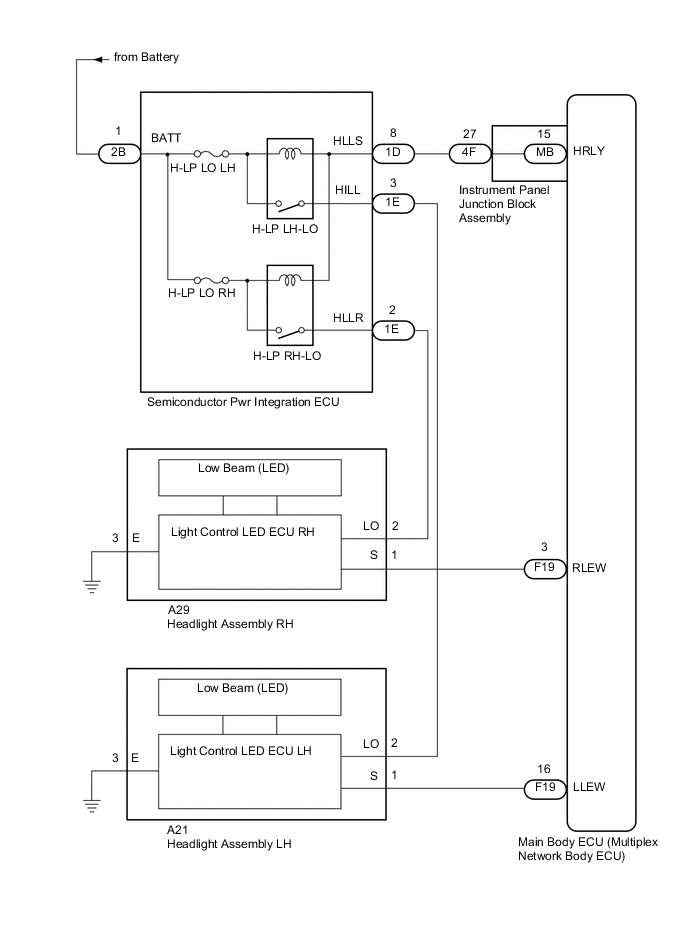
These DTCs are stored when the low beam headlights do not illuminate, or a communication malfunction is detected between the headlight assembly and main body ECU (multiplex network body ECU).
| DTC No. | Detection Item | DTC Detection Condition | Trouble Area |
|---|---|---|---|
| B2430 | LED Headlight LH Circuit Malfunction | Any of the following conditions occur after 20 seconds have elapsed since the ignition switch was turned ON:
|
|
| B2431 | LED Headlight RH Circuit Malfunction | Any of the following conditions occur after 20 seconds have elapsed since the ignition switch was turned ON:
|
|
WIRING DIAGRAM
CAUTION / NOTICE / HINT
Note
-
Inspect the fuses for circuits related to this system before performing the following inspection procedure.
-
DTC B2430 and B2431 are not output if 20 seconds have not elapsed since the ignition switch was turned ON.
-
If the main body ECU (multiplex network body ECU) is replaced, refer to Service Bulletin.*
-
*: w/ Smart Entry and Start System
-
As the door control battery is installed between the vehicle battery and main body ECU (multiplex network body ECU), first perform the inspections in On-Vehicle Inspection to confirm that there are no malfunctions in the power source circuit for the main body ECU (multiplex network body ECU) before performing this troubleshooting procedure.*
-
*: for LHD
PROCEDURE
-
CHECK FOR DTC
-
Clear the DTCs.
Body Electrical > Main Body > Clear DTCs -
Check for DTCs.
Body Electrical > Main Body > Trouble CodesResult Result Proceed to Both DTC B2430 and B2431 are not output. A Both DTC B2430 and B2431 are output. B Only DTC B2430 or B2431 is output. C
A 
USE SIMULATION METHOD TO CHECK Click here
C 
CHECK HARNESS AND CONNECTOR (SEMICONDUCTOR PWR INTEGRATION ECU - HEADLIGHT ASSEMBLY) Click here
B 
-
-
INSPECT SEMICONDUCTOR PWR INTEGRATION ECU
-
Remove the semiconductor pwr integration ECU from the No. 1 engine room relay block and No. 1 junction block assembly.
-
Inspect the semiconductor pwr integration ECU.
OK Semiconductor pwr integration ECU is normal. Result Proceed to OK NG
NG
REPLACE SEMICONDUCTOR PWR INTEGRATION ECU Click here
OK
-
-
CHECK HARNESS AND CONNECTOR (SEMICONDUCTOR PWR INTEGRATION ECU - BATTERY)
-
Measure the voltage according to the value(s) in the table below.
Standard Voltage Tester Connection Condition Specified Condition 2B-1 (BATT) - Body ground Always 11 to 14 V Result Proceed to OK NG
NG
REPAIR OR REPLACE HARNESS OR CONNECTOR
OK
-
-
CHECK HARNESS AND CONNECTOR (SEMICONDUCTOR PWR INTEGRATION ECU - INSTRUMENT PANEL JUNCTION BLOCK ASSEMBLY)
-
Disconnect the 1D instrument panel junction block assembly connector.
-
Measure the resistance according to the value(s) in the table below.
Standard Resistance Tester Connection Condition Specified Condition 1D-8 (HLLS) - 4F-27 Always Below 1 Ω 1D-8 (HLLS) - Body ground Always 10 kΩ or higher Result Proceed to OK NG
NG
REPAIR OR REPLACE HARNESS OR CONNECTOR
OK
-
-
INSPECT INSTRUMENT PANEL JUNCTION BLOCK ASSEMBLY
-
Remove the instrument panel junction block assembly.
-
Remove the main body ECU (multiplex network body ECU) from the instrument panel junction block assembly.
-
Measure the resistance according to the value(s) in the table below.
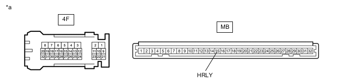
*a Component without harness connected
(Instrument Panel Junction Block Assembly)
- - Standard Resistance Tester Connection Condition Specified Condition 4F-27 - MB-15 (HRLY) Always Below 1 Ω Result Proceed to OK NG
OK
REPLACE MAIN BODY ECU (MULTIPLEX NETWORK BODY ECU) Click here
NG
REPLACE INSTRUMENT PANEL JUNCTION BLOCK ASSEMBLY Click here
-
-
CHECK HARNESS AND CONNECTOR (SEMICONDUCTOR PWR INTEGRATION ECU - HEADLIGHT ASSEMBLY)
-
Disconnect the A21*1 or A29*2 headlight assembly connector.
-
*1: for LH Side
-
*2: for RH Side
-
-
Measure the voltage according to the value(s) in the table below.
Standard Voltage for LH Side (B2430) Tester Connection Condition Specified Condition A21-2 (LO) - Body ground Ignition switch off, light control switch in head position 11 to 14 V for RH Side (B2431) Tester Connection Condition Specified Condition A29-2 (LO) - Body ground Ignition switch off, light control switch in head position 11 to 14 V Result Proceed to OK NG
NG
INSPECT SEMICONDUCTOR PWR INTEGRATION ECU Click here
OK
-
-
CHECK HARNESS AND CONNECTOR (HEADLIGHT ASSEMBLY - BODY GROUND)
-
Measure the resistance according to the value(s) in the table below.
Standard Resistance for LH Side (B2430) Tester Connection Condition Specified Condition A21-3 (E) - Body ground Always Below 1 Ω for RH Side (B2431) Tester Connection Condition Specified Condition A29-3 (E) - Body ground Always Below 1 Ω Result Proceed to OK NG
NG
REPAIR OR REPLACE HARNESS OR CONNECTOR
OK
-
-
CHECK HARNESS AND CONNECTOR (HEADLIGHT ASSEMBLY - MAIN BODY ECU (MULTIPLEX NETWORK BODY ECU))
-
Measure the voltage according to the value(s) in the table below.
Standard Voltage for LH Side (B2430) Tester Connection Condition Specified Condition A21-1 (S) - Body ground Ignition switch ON, light control switch in head position 11 to 14 V for RH Side (B2431) Tester Connection Condition Specified Condition A29-1 (S) - Body ground Ignition switch ON, light control switch in head position 11 to 14 V Result Proceed to OK NG
NG
CHECK HARNESS AND CONNECTOR (HEADLIGHT ASSEMBLY - MAIN BODY ECU (MULTIPLEX NETWORK BODY ECU)) Click here
OK
-
-
CHECK LIGHT CONTROL ECU
-
Temporarily replace the light control LED ECU with a new or known good one.
-
Check for DTCs.
Body Electrical > Main Body > Trouble CodesResult Result Proceed to Both DTC B2430 and B2431 are not output. A Only DTC B2430 or B2431 is output. B
A
END (LIGHT CONTROL LED ECU WAS DEFECTIVE)
B
-
-
CHECK HEADLIGHT UNIT
-
Temporarily replace the headlight unit with a new or known good one.
-
Check for DTCs.
Body Electrical > Main Body > Trouble CodesResult Result Proceed to Both DTC B2430 and B2431 are not output. A Only DTC B2430 or B2431 is output. B
A
END (HEADLIGHT UNIT WAS DEFECTIVE)
B
REPLACE MAIN BODY ECU (MULTIPLEX NETWORK BODY ECU) Click here
-
-
CHECK HARNESS AND CONNECTOR (HEADLIGHT ASSEMBLY - MAIN BODY ECU (MULTIPLEX NETWORK BODY ECU))
-
Disconnect the F19 main body ECU (multiplex network body ECU) connector.
-
Measure the resistance according to the value(s) in the table below.
Standard Resistance for LH Side (B2430) Tester Connection Condition Specified Condition A21-1 (S) - F19-16 (LLEW) Always Below 1 Ω A21-1 (S) - Body ground Always 10 kΩ or higher for RH Side (B2431) Tester Connection Condition Specified Condition A29-1 (S) - F19-3 (RLEW) Always Below 1 Ω A29-1 (S) - Body ground Always 10 kΩ or higher Result Proceed to OK NG
OK
REPLACE MAIN BODY ECU (MULTIPLEX NETWORK BODY ECU) Click here
NG
REPAIR OR REPLACE HARNESS OR CONNECTOR
-
-
INSPECT SEMICONDUCTOR PWR INTEGRATION ECU
-
Remove the semiconductor pwr integration ECU from the No. 1 engine room relay block and No. 1 junction block assembly.
-
Inspect the semiconductor pwr integration ECU.
OK Semiconductor pwr integration ECU is normal. Result Proceed to OK NG
OK
REPAIR OR REPLACE HARNESS OR CONNECTOR (HEADLIGHT ASSEMBLY - SEMICONDUCTOR POWER INTEGRATION ECU)
NG
REPLACE SEMICONDUCTOR PWR INTEGRATION ECU Click here
-