WIPER AND WASHER SYSTEM Rain Sensor Circuit
DESCRIPTION
The windshield wiper relay assembly receives a signal from the rain sensor via LIN communication to control the auto wiper system.
WIRING DIAGRAM
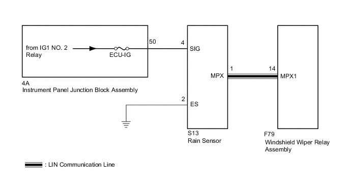
CAUTION / NOTICE / HINT
Note
Inspect the fuses for circuits related to this system before performing the following inspection procedure.
PROCEDURE
-
CHECK HARNESS AND CONNECTOR (RAIN SENSOR - IG CIRCUIT AND BODY GROUND)
-
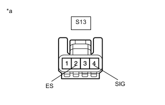
*a Front view of wire harness connector
(to Rain Sensor)
Disconnect the S13 rain sensor connector.
-
Measure the voltage according to the value(s) in the table below.
Standard Voltage Tester Connection Condition Specified Condition S13-4 (SIG) - Body ground Ignition switch ON 11 to 14 V Ignition switch off Below 1 V -
Measure the resistance according to the value(s) in the table below.
Standard Resistance Tester Connection Condition Specified Condition S13-2 (ES) - Body ground Always Below 1 Ω Result Proceed to OK NG
NG 
CHECK HARNESS AND CONNECTOR (RAIN SENSOR - INSTRUMENT PANEL JUNCTION BLOCK ASSEMBLY) Click here
OK 
-
-
CHECK HARNESS AND CONNECTOR (WINDSHIELD WIPER RELAY ASSEMBLY - RAIN SENSOR)
-
Disconnect the F79 windshield wiper relay assembly connector.
-
Measure the resistance according to the value(s) in the table below.
Standard Resistance Tester Connection Condition Specified Condition F79-14 (MPX1) - S13-1 (MPX) Always Below 1 Ω F79-14 (MPX1) or S13-1 (MPX) - Body ground Always 10 kΩ or higher Result Proceed to OK NG
NG 
REPAIR OR REPLACE HARNESS OR CONNECTOR
OK
-
-
INSPECT RAIN SENSOR
-
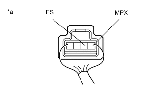
*a Component with harness connected
(Rain Sensor)
Connect the S13 rain sensor connector.
-
Connect an oscilloscope to the rain sensor connector.
-
Check for pulses.
OK Tester Connection Condition Specified Condition 1 (MPX) - 2 (ES) Ignition switch ON Pulse generation Result Proceed to OK NG
OK
PROCEED TO NEXT SUSPECTED AREA SHOWN IN PROBLEM SYMPTOMS TABLE Click here
NG
REPLACE RAIN SENSOR Click here
-
-
CHECK HARNESS AND CONNECTOR (RAIN SENSOR - INSTRUMENT PANEL JUNCTION BLOCK ASSEMBLY)
-
Disconnect the 4A instrument panel junction block assembly connector.
-
Measure the resistance according to the value(s) in the table below.
Standard Resistance Tester Connection Condition Specified Condition S13-4 (SIG) - 4A-50 Always Below 1 Ω S13-4 (SIG) or 4A-50 - Body ground Always 10 kΩ or higher Result Proceed to OK NG
OK
REPLACE INSTRUMENT PANEL JUNCTION BLOCK ASSEMBLY Click here
NG
REPAIR OR REPLACE HARNESS OR CONNECTOR
-