WIPER AND WASHER SYSTEM Wiper and Washer Switch Circuit
DESCRIPTION
This circuit detects the state of the windshield wiper switch assembly (front wiper switch and front washer switch) and sends it to the windshield wiper relay assembly.
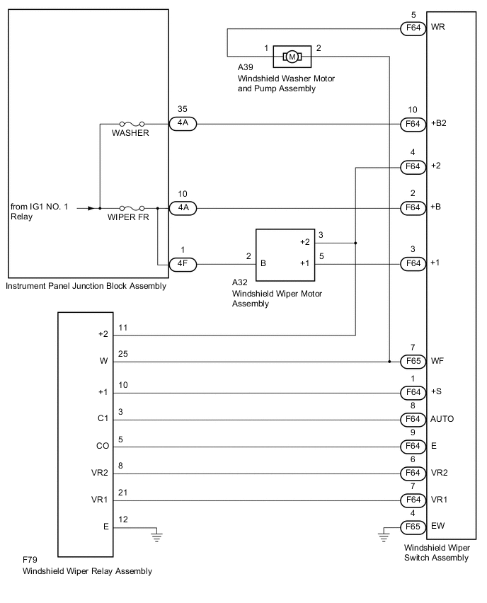
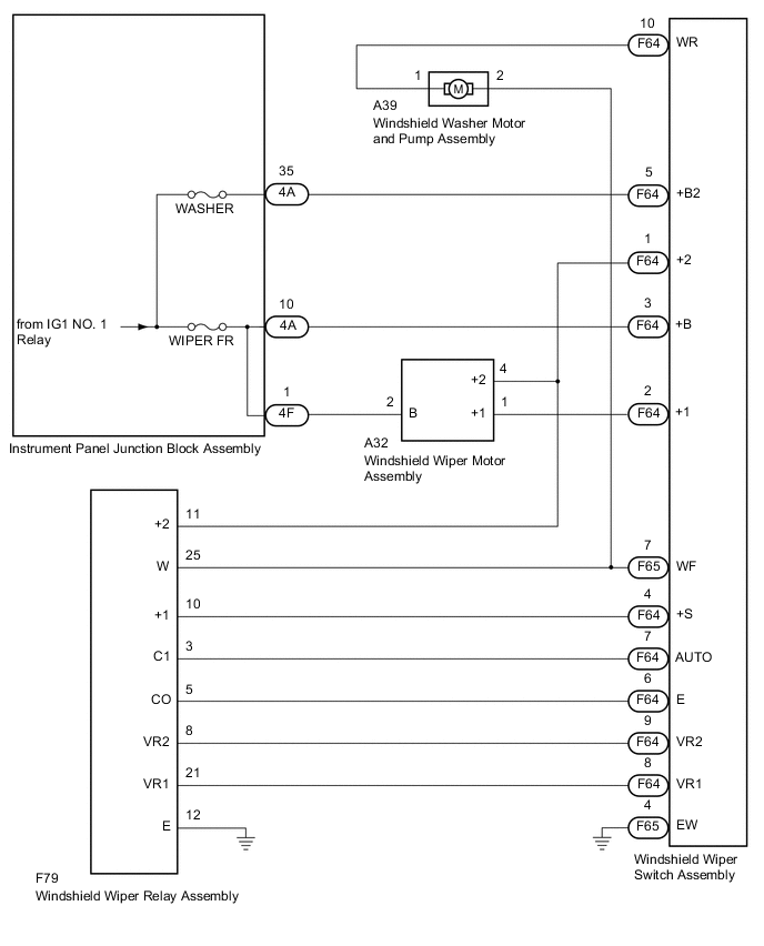
WIRING DIAGRAM
-
for LHD
-
for RHD
CAUTION / NOTICE / HINT
Note
Inspect the fuses for circuits related to this system before performing the following inspection procedure.
PROCEDURE
-
CHECK HARNESS AND CONNECTOR (WINDSHIELD WIPER SWITCH ASSEMBLY - IG CIRCUIT)
-
for LHD:
-
Disconnect the F64 windshield wiper switch assembly connector.
-
Measure the voltage according to the value(s) in the table below.
Standard Voltage Tester Connection Condition Specified Condition F64-2 (+B) - Body ground Ignition switch off Below 1 V Ignition switch ON 11 to 14 V F64-10 (+B2) - Body ground Ignition switch off Below 1 V Ignition switch ON 11 to 14 V
-
-
for RHD:
-
Disconnect the F64 windshield wiper switch assembly connector.
-
Measure the voltage according to the value(s) in the table below.
Standard Voltage Tester Connection Condition Specified Condition F64-3 (+B) - Body ground Ignition switch off Below 1 V Ignition switch ON 11 to 14 V F64-5 (+B2) - Body ground Ignition switch off Below 1 V Ignition switch ON 11 to 14 V
Result Proceed to OK NG -
NG 
CHECK HARNESS AND CONNECTOR (WINDSHIELD WIPER SWITCH ASSEMBLY - INSTRUMENT PANEL JUNCTION BLOCK ASSEMBLY) Click here
OK 
-
-
CHECK HARNESS AND CONNECTOR (WINDSHIELD WIPER SWITCH ASSEMBLY - BODY GROUND)
-
Disconnect the F65 windshield wiper switch assembly connector.
-
Measure the resistance according to the value(s) in the table below.
Standard Resistance Tester Connection Condition Specified Condition F65-4 (EW) - Body ground Always Below 1 Ω Result Proceed to OK NG
NG 
REPAIR OR REPLACE HARNESS OR CONNECTOR
OK
-
-
INSPECT WINDSHIELD WIPER SWITCH ASSEMBLY
-
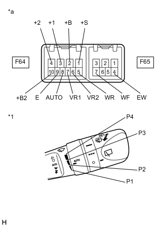
*1 Windshield Wiper Switch Assembly (Adjusting Ring Position) *a Component without harness connected
(Windshield Wiper Switch Assembly)
for LHD:
-
Remove the windshield wiper switch assembly.
-
Measure the resistance according to the value(s) in the table below.
Standard Resistance Front Wiper Switch Tester Connection Condition Specified Condition F64-2 (+B) - F64-3 (+1) MIST Below 1 Ω F64-3 (+1) - F64-1 (+S) OFF F64-3 (+1) - F64-1 (+S) AUTO F64-8 (AUTO) - F64-9 (E) F64-2 (+B) - F64-3 (+1) LO F64-2 (+B) - F64-4 (+2) HI Front Washer Switch Tester Connection Condition Specified Condition F65-4 (EW) - F65-7 (WF) ON Below 1 Ω F64-5 (WR) - F64-10 (+B2) F65-4 (EW) - F65-7 (WF) OFF 10 kΩ or higher F64-5 (WR) - F64-10 (+B2) Adjusting Ring* Tester Connection Condition Specified Condition F64-6 (VR2) - F64-7 (VR1) P1 209 to 231 Ω P2 114 to 126 Ω P3 58.9 to 65.1 Ω P4 Below 1 Ω Tech Tips
*: The rain sensor sensitivity can be adjusted by the windshield wiper switch assembly adjusting ring.
-
-
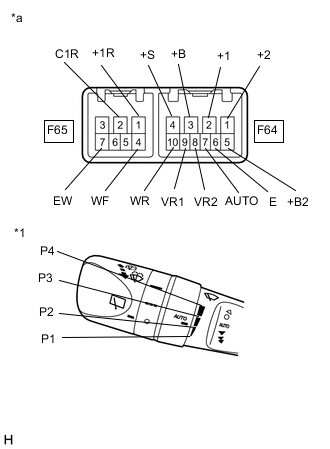
*1 Windshield Wiper Switch Assembly (Adjusting Ring Position) *a Component without harness connected
(Windshield Wiper Switch Assembly)
for RHD:
-
Remove the windshield wiper switch assembly.
-
Measure the resistance according to the value(s) in the table below.
Standard Resistance Front Wiper Switch Tester Connection Condition Specified Condition F64-3 (+B) - F64-2 (+1) MIST Below 1 Ω F64-2 (+1) - F64-4 (+S) OFF F64-2 (+1) - F64-4 (+S) AUTO F64-7 (AUTO) - F64-6 (E) F64-3 (+B) - F64-2 (+1) LO F64-3 (+B) - F64-1 (+2) HI Front Washer Switch Tester Connection Condition Specified Condition F65-7 (EW) - F65-4 (WF) ON Below 1 Ω F64-10 (WR) - F64-5 (+B2) F65-7 (EW) - F65-4 (WF) OFF 10 kΩ or higher F64-10 (WR) - F64-5 (+B2) Adjusting Ring* Tester Connection Condition Specified Condition F64-8 (VR2) - F64-9 (VR1) P1 209 to 231 Ω P2 114 to 126 Ω P3 58.9 to 65.1 Ω P4 Below 1 Ω Tech Tips
*: The rain sensor sensitivity can be adjusted by the windshield wiper switch assembly adjusting ring.
Result Proceed to OK NG -
NG
REPLACE WINDSHIELD WIPER SWITCH ASSEMBLY Click here
OK
-
-
CHECK HARNESS AND CONNECTOR (WINDSHIELD WIPER SWITCH ASSEMBLY - WINDSHIELD WIPER RELAY ASSEMBLY)
-
for LHD:
-
Disconnect the F79 windshield wiper relay assembly connector.
-
Measure the resistance according to the value(s) in the table below.
Standard Resistance Tester Connection Condition Specified Condition F64-1 (+S) - F79-10 (+1) Always Below 1 Ω F64-1 (+S) or F79-10 (+1) - Body ground Always 10 kΩ or higher F64-9 (E) - F79-5 (CO) Always Below 1 Ω F64-9 (E) or F79-5 (CO) - Body ground Always 10 kΩ or higher F64-8 (AUTO) - F79-3 (C1) Always Below 1 Ω F64-8 (AUTO) or F79-3 (C1) - Body ground Always 10 kΩ or higher F64-6 (VR2) - F79-8 (VR2) Always Below 1 Ω F64-6 (VR2) or F79-8 (VR2) - Body ground Always 10 kΩ or higher F64-7 (VR1) - F79-21 (VR1) Always Below 1 Ω F64-7 (VR1) or F79-21 (VR1) - Body ground Always 10 kΩ or higher
-
-
for RHD:
-
Disconnect the F79 windshield wiper relay assembly connector.
-
Measure the resistance according to the value(s) in the table below.
Standard Resistance Tester Connection Condition Specified Condition F64-4 (+S) - F79-10 (+1) Always Below 1 Ω F64-4 (+S) or F79-10 (+1) - Body ground Always 10 kΩ or higher F64-6 (E) - F79-5 (CO) Always Below 1 Ω F64-6 (E) or F79-5 (CO) - Body ground Always 10 kΩ or higher F64-7 (AUTO) - F79-3 (C1) Always Below 1 Ω F64-7 (AUTO) or F79-3 (C1) - Body ground Always 10 kΩ or higher F64-9 (VR2) - F79-8 (VR2) Always Below 1 Ω F64-9 (VR2) or F79-8 (VR2) - Body ground Always 10 kΩ or higher F64-8 (VR1) - F79-21 (VR1) Always Below 1 Ω F64-8 (VR1) or F79-21 (VR1) - Body ground Always 10 kΩ or higher
Result Proceed to OK NG -
NG
REPAIR OR REPLACE HARNESS OR CONNECTOR
OK
-
-
CHECK HARNESS AND CONNECTOR (WINDSHIELD WIPER SWITCH ASSEMBLY - WINDSHIELD WIPER RELAY ASSEMBLY)
-
Disconnect the A39 windshield washer motor and pump assembly connector.
-
Measure the resistance according to the value(s) in the table below.
Standard Resistance Tester Connection Condition Specified Condition F65-7 (WF) - F79-25 (W) Always Below 1 Ω F65-7 (WF) or F79-25 (W) - Body ground Always 10 kΩ or higher Result Proceed to OK NG
NG
REPAIR OR REPLACE HARNESS OR CONNECTOR
OK
-
-
CHECK HARNESS AND CONNECTOR (WINDSHIELD WIPER SWITCH ASSEMBLY - WINDSHIELD WASHER MOTOR AND PUMP ASSEMBLY)
-
for LHD:
-
Measure the resistance according to the value(s) in the table below.
Standard Resistance Tester Connection Condition Specified Condition F65-7 (WF) - A39-2 Always Below 1 Ω F64-5 (WR) - A39-1 Always Below 1 Ω F65-7 (WF) or A39-2 - Body ground Always 10 kΩ or higher F64-5 (WR) or A39-1 - Body ground Always 10 kΩ or higher
-
-
for RHD:
-
Measure the resistance according to the value(s) in the table below.
Standard Resistance Tester Connection Condition Specified Condition F65-7 (WF) - A39-2 Always Below 1 Ω F64-10 (WR) - A39-1 Always Below 1 Ω F65-7 (WF) or A39-2 - Body ground Always 10 kΩ or higher F64-10 (WR) or A39-1 - Body ground Always 10 kΩ or higher
Result Proceed to OK NG -
NG
REPAIR OR REPLACE HARNESS OR CONNECTOR
OK
-
-
CHECK HARNESS AND CONNECTOR (WINDSHIELD WIPER SWITCH ASSEMBLY - WINDSHIELD WIPER MOTOR ASSEMBLY)
-
for LHD:
-
Disconnect the A32 windshield wiper motor assembly connector.
-
Measure the resistance according to the value(s) in the table below.
Standard Resistance Tester Connection Condition Specified Condition F64-3 (+1) - A32-5 (+1) Always Below 1 Ω F64-4 (+2) - A32-3 (+2) Always Below 1 Ω F64-3 (+1) or A32-5 (+1) - Body ground Always 10 kΩ or higher F64-4 (+2) or A32-3 (+2) - Body ground Always 10 kΩ or higher
-
-
for RHD:
-
Disconnect the A32 windshield wiper motor assembly connector.
-
Measure the resistance according to the value(s) in the table below.
Standard Resistance Tester Connection Condition Specified Condition F64-2 (+1) - A32-1 (+1) Always Below 1 Ω F64-1 (+2) - A32-4 (+2) Always Below 1 Ω F64-2 (+1) or A32-1 (+1) - Body ground Always 10 kΩ or higher F64-1 (+2) or A32-4 (+2) - Body ground Always 10 kΩ or higher
Result Proceed to OK NG -
NG
REPAIR OR REPLACE HARNESS OR CONNECTOR
OK
-
-
CHECK HARNESS AND CONNECTOR (WINDSHIELD WIPER SWITCH ASSEMBLY - WINDSHIELD WIPER RELAY ASSEMBLY)
-
for LHD:
-
Measure the resistance according to the value(s) in the table below.
Standard Resistance Tester Connection Condition Specified Condition F64-4 (+2) - F79-11 (+2) Always Below 1 Ω F64-4 (+2) or F79-11 (+2) - Body ground Always 10 kΩ or higher
-
-
for RHD:
-
Measure the resistance according to the value(s) in the table below.
Standard Resistance Tester Connection Condition Specified Condition F64-1 (+2) - F79-11 (+2) Always Below 1 Ω F64-1 (+2) or F79-11 (+2) - Body ground Always 10 kΩ or higher
Result Proceed to OK NG -
NG
REPAIR OR REPLACE HARNESS OR CONNECTOR
OK
-
-
CHECK HARNESS AND CONNECTOR (WINDSHIELD WIPER MOTOR ASSEMBLY - INSTRUMENT PANEL JUNCTION BLOCK ASSEMBLY)
-
Disconnect the 4F instrument panel junction block assembly connector.
-
Measure the resistance according to the value(s) in the table below.
Standard Resistance Tester Connection Condition Specified Condition A32-2 (B) - 4F-1 Always Below 1 Ω A32-2 (B) or 4F-1 - Body ground Always 10 kΩ or higher Result Proceed to OK NG
NG
REPAIR OR REPLACE HARNESS OR CONNECTOR
OK
-
-
INSPECT INSTRUMENT PANEL JUNCTION BLOCK ASSEMBLY
-
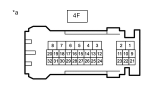
*a Component without harness connected
(Instrument Panel Junction Block Assembly)
Remove the instrument panel junction block assembly.
-
Measure the resistance according to the value(s) in the table below.
Standard Resistance Tester Connection Condition Specified Condition 4F-1 - 4F-10 Always Below 1 Ω Result Proceed to OK NG
OK
PROCEED TO NEXT SUSPECTED AREA SHOWN IN PROBLEM SYMPTOMS TABLE Click here
NG
REPLACE INSTRUMENT PANEL JUNCTION BLOCK ASSEMBLY Click here
-
-
CHECK HARNESS AND CONNECTOR (WINDSHIELD WIPER SWITCH ASSEMBLY - INSTRUMENT PANEL JUNCTION BLOCK ASSEMBLY)
-
for LHD:
-
Disconnect the 4A instrument panel junction block assembly connectors.
-
Measure the resistance according to the value(s) in the table below.
Standard Resistance Tester Connection Condition Specified Condition F64-2 (+B) - 4A-10 Always Below 1 Ω F64-10 (+B2) - 4A-35 Always Below 1 Ω F64-2 (+B) or 4A-10 - Body ground Always 10 kΩ or higher F64-10 (+B2) or 4A-35 - Body ground Always 10 kΩ or higher
-
-
for RHD:
-
Disconnect the 4A instrument panel junction block assembly connectors.
-
Measure the resistance according to the value(s) in the table below.
Standard Resistance Tester Connection Condition Specified Condition F64-3 (+B) - 4A-10 Always Below 1 Ω F64-5 (+B2) - 4A-35 Always Below 1 Ω F64-3 (+B) or 4A-10 - Body ground Always 10 kΩ or higher F64-5 (+B2) or 4A-35 - Body ground Always 10 kΩ or higher
Result Proceed to OK NG -
OK
REPLACE INSTRUMENT PANEL JUNCTION BLOCK ASSEMBLY Click here
NG
REPAIR OR REPLACE HARNESS OR CONNECTOR
-