POWER MIRROR CONTROL SYSTEM(w/o Memory) Mirror Heater does not Operate with Rear Defogger Switch
DESCRIPTION
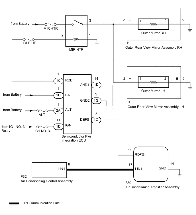
When the mirror heater switch (rear window defogger switch) on the air conditioning control assembly is pressed, the operation signal is sent to the air conditioning amplifier assembly via LIN communication. When the air conditioning amplifier assembly receives the signal, it turns on a relay in the semiconductor power integration ECU to operate the mirror heaters.
WIRING DIAGRAM
CAUTION / NOTICE / HINT
Note
-
If the battery voltage is low, the mirror heater function may not operate. In this case, check the Data List item "Battery Control Count (Body ECU)".
-
Inspect the fuses for circuits related to this system before performing the following procedure.
PROCEDURE
-
PERFORM ACTIVE TEST USING GTS
-
Connect the GTS to the DLC3.
-
Turn the ignition switch to ON.
-
Turn the GTS on.
-
Enter the following menus: Body Electrical / Air Conditioner / Active Test.
-
Perform the Active Test according to the display on the GTS.
Body Electrical > Air Conditioner > Active TestTester Display Measurement Item Control Range Diagnostic Note Defogger Relay (Rear) Mirror heater operation OFF or ON -
Body Electrical > Air Conditioner > Active TestTester Display Defogger Relay (Rear) Result Result Proceed to Mirror heater operation on both mirrors is not normal A Mirror heater operation on RH side mirror is not normal B Mirror heater operation on LH side mirror is not normal C
B 
CHECK HARNESS AND CONNECTOR (MIR HTR RELAY - OUTER REAR VIEW MIRROR ASSEMBLY RH - BODY GROUND) Click here
C
CHECK HARNESS AND CONNECTOR (MIR HTR RELAY - OUTER REAR VIEW MIRROR ASSEMBLY LH - BODY GROUND) Click here
A 
-
-
CHECK WINDOW DEFOGGER SYSTEM
-
Check the window defogger system operation.
OK The window defogger system operates normally. Result Proceed to OK NG
NG 
GO TO WINDOW DEFOGGER SYSTEM Click here
OK
-
-
INSPECT MIR HTR RELAY
-
Remove the MIR HTR relay from the relay block No. 5.
-
Inspect the MIR HTR relay.
Result Proceed to OK NG
NG
REPLACE MIR HTR RELAY
OK
-
-
CHECK HARNESS AND CONNECTOR (MIR HTR RELAY - SEMICONDUCTOR PWR INTEGRATION ECU)
-
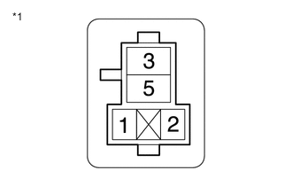
*1 Relay Block No. 5 Measure the resistance according to the value(s) in the table below.
Standard Resistance Tester Connection Condition Specified Condition Relay block No. 5 MIR HTR relay terminal 2 - 1C-1 (RDEF) Always Below 1 Ω Relay block No. 5 MIR HTR relay terminal 2 or 1C-1 (RDEF) - Body ground Always 10 kΩ or higher Relay block No. 5 MIR HTR relay terminal 1 - Body ground Always Below 1 Ω Result Proceed to OK NG
NG
REPAIR OR REPLACE HARNESS OR CONNECTOR
OK
-
-
CHECK HARNESS AND CONNECTOR (MIR HTR RELAY POWER SOURCE)
-
*1 Relay Block No. 5 Measure the voltage according to the value(s) in the table below.
Standard Voltage Tester Connection Condition Specified Condition Relay block No. 5 MIR HTR relay terminal 2 - Body ground Ignition switch ON, rear defogger switch on 11 to 14 V Relay block No. 5 MIR HTR relay terminal 5 - Body ground Always 11 to 14 V Result Proceed to OK NG
NG
REPAIR OR REPLACE HARNESS OR CONNECTOR
OK
-
-
CHECK HARNESS AND CONNECTOR (MIR HTR RELAY - OUTER REAR VIEW MIRROR ASSEMBLY RH/LH - BODY GROUND)
-
Disconnect the H1 outer rear view mirror assembly RH connector.
-
Disconnect the I1 outer rear view mirror assembly LH connector.
-
Measure the resistance according to the value(s) in the table below.
Standard Resistance Tester Connection Condition Specified Condition Relay block No. 5 MIR HTR relay terminal 3 - H1-2 (+) Always Below 1 Ω Relay block No. 5 MIR HTR relay terminal 3 - I1-2 (+) Always Below 1 Ω H1-2 (+), I1-2 (+) or Relay block No. 5 MIR HTR relay terminal 3 - Body ground Always 10 kΩ or higher Result Proceed to OK NG
OK
USE SIMULATION METHOD TO CHECK Click here
NG
REPAIR OR REPLACE HARNESS OR CONNECTOR
-
-
CHECK HARNESS AND CONNECTOR (MIR HTR RELAY - OUTER REAR VIEW MIRROR ASSEMBLY RH - BODY GROUND)
-
*1 Relay Block No. 5 Remove the MIR HTR relay from relay block No. 5.
-
Disconnect the H1 outer rear view mirror assembly RH connector.
-
Disconnect the I1 outer rear view mirror assembly LH connector.
-
Measure the resistance according to the value(s) in the table below.
Standard Resistance Tester Connection Condition Specified Condition Relay block No. 5 MIR HTR relay terminal 3 - H1-2 (+) Always Below 1 Ω H1-9 (E) - Body Ground Always Below 1 Ω Relay block No. 5 MIR HTR relay terminal 3 or H1-2 (+) - Body Ground Always 10 kΩ or higher Result Proceed to OK NG
NG
REPAIR OR REPLACE HARNESS OR CONNECTOR
OK
-
-
INSPECT OUTER MIRROR RH (MIRROR HEATER)
-
Remove the outer mirror RH.
-
Inspect the outer mirror RH.
OK Outer mirror RH is normal. Result Proceed to OK NG
OK
REPLACE OUTER REAR VIEW MIRROR ASSEMBLY RH Click here
NG
REPLACE OUTER MIRROR RH Click here
-
-
CHECK HARNESS AND CONNECTOR (MIR HTR RELAY - OUTER REAR VIEW MIRROR ASSEMBLY LH - BODY GROUND)
-
*1 Relay Block No. 5 Remove the MIR HTR relay from the relay block No. 5.
-
Disconnect the H1 outer rear view mirror assembly RH connector.
-
Disconnect the I1 outer rear view mirror assembly LH connector.
-
Measure the resistance according to the value(s) in the table below.
Standard Resistance Tester Connection Condition Specified Condition Relay block No. 5 MIR HTR relay terminal 3 - I1-2 (+) Always Below 1 Ω I1-9 (E) - Body Ground Always Below 1 Ω Relay block No. 5 MIR HTR relay terminal 3 or I1-2 (+) - Body Ground Always 10 kΩ or higher Result Proceed to OK NG
NG
REPAIR OR REPLACE HARNESS OR CONNECTOR
OK
-
-
INSPECT OUTER MIRROR LH (MIRROR HEATER)
-
Remove the outer mirror LH.
-
Inspect the outer mirror LH.
OK Outer mirror LH is normal. Result Proceed to OK NG
OK
REPLACE OUTER REAR VIEW MIRROR ASSEMBLY LH Click here
NG
REPLACE OUTER MIRROR LH Click here
-