POWER MIRROR CONTROL SYSTEM(w/ Memory) Power Mirror Surface Position is not Memorized
DESCRIPTION
If any of the M1 or M2 seat memory switch is pressed, the outer mirror control ECU assembly (driver door) detects the switch operation and sends the seat memory switch signal to the main body ECU (multiplex network body ECU) via CAN communication. On receiving the seat memory switch signal, the main body ECU (multiplex network body ECU) sends the memory request signal to each outer mirror control ECU assembly via CAN communication. When receiving this signal, each outer mirror control ECU assembly stores the mirror surface position based on information from the mirror position sensor, which is built into the outer rear view mirror assembly.
WIRING DIAGRAM
-
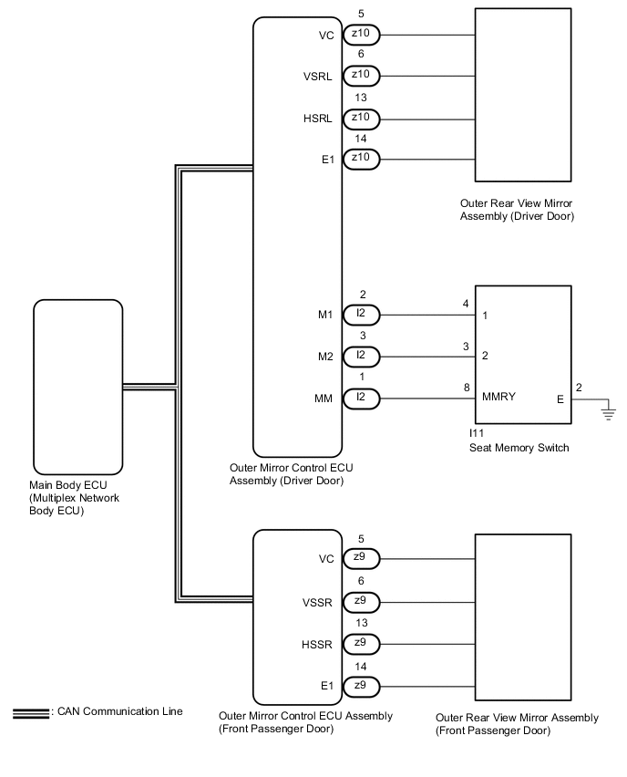
for LHD
-
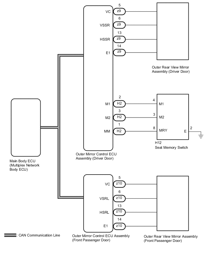
for RHD
CAUTION / NOTICE / HINT
Note
-
The power mirror control system (w/ Memory) uses the CAN communication system. Inspect the communication function by following How to Proceed with Troubleshooting. Troubleshoot the power mirror control system (w/ Memory) after confirming that the communication systems are functioning properly.
-
Before replacing the main body ECU (multiplex network body ECU), refer to Service Bulletin.
-
The mirror surface position will not be memorized if the ignition switch is not ON.
-
The mirror surface position will not be stored if the seat memory SET switch and 2 or more seat memory switches are pressed simultaneously.
-
If the operation fails, the mirror surface position will not be memorized until the seat memory SET switch is released and the operation is attempted again.
-
The mirror surface position will not be memorized when the mirror is operated manually.
-
As the door control battery is installed between the vehicle battery and main body ECU (multiplex network body ECU), first perform the inspections in On-Vehicle Inspection to confirm that there are no malfunctions in the power source circuit for the main body ECU (multiplex network body ECU) before performing this troubleshooting procedure.*
-
*: for LHD
Tech Tips
Each outer rear view mirror assembly has a built-in mirror vertical position sensor and mirror horizontal position sensor.
PROCEDURE
-
READ VALUE USING GTS
-
Connect the GTS to the DLC3.
-
Turn the ignition switch to ON.
-
Turn the GTS on.
-
Enter the following menus: Body Electrical / Mirror L*1 or Mirror R*2 / Data List.
-
*1: for LHD
-
*2: for RHD
-
-
Read the Data List according to the display on the GTS.
-
for LHD
Body Electrical > Mirror L > Data ListTester Display Measurement Item Range Normal Condition Diagnostic Note Seat Memory Switch1 Seat memory switch M1 switch signal OFF or ON OFF: Seat memory switch M1 switch off
ON: Seat memory switch M1 switch on
- Seat Memory Switch2 Seat memory switch M2 switch signal OFF or ON OFF: Seat memory switch M2 switch off
ON: Seat memory switch M2 switch on
- Seat Memory Switch3 Seat memory switch M3 switch signal* OFF or ON OFF: Seat memory switch M3 switch off
ON: Seat memory switch M3 switch on
Not applicable Seat Memory Set SW Seat memory switch SET switch signal OFF or ON OFF: Seat memory switch SET switch off
ON: Seat memory switch SET switch on
-
-
*: Although the item is displayed on the GTS, it is not applicable to this vehicle.
Body Electrical > Mirror L > Data ListTester Display Seat Memory Switch1 Seat Memory Switch2 Seat Memory Switch3 Seat Memory Set SW -
-
for RHD
Body Electrical > Mirror R > Data ListTester Display Measurement Item Range Normal Condition Diagnostic Note Seat Memory Switch1 Seat memory switch M1 switch signal OFF or ON OFF: Seat memory switch M1 switch off
ON: Seat memory switch M1 switch on
- Seat Memory Switch2 Seat memory switch M2 switch signal OFF or ON OFF: Seat memory switch M2 switch off
ON: Seat memory switch M2 switch on
- Seat Memory Switch3 Seat memory switch M3 switch signal* OFF or ON OFF: Seat memory switch M3 switch off
ON: Seat memory switch M3 switch on
Not applicable Seat Memory Set SW Seat memory switch SET switch signal OFF or ON OFF: Seat memory switch SET switch off
ON: Seat memory switch SET switch on
-
-
*: Although the item is displayed on the GTS, it is not applicable to this vehicle.
Body Electrical > Mirror R > Data ListTester Display Seat Memory Switch1 Seat Memory Switch2 Seat Memory Switch3 Seat Memory Set SW -
OK On the GTS screen, ON or OFF is displayed accordingly. Result Proceed to OK NG -
NG 
INSPECT SEAT MEMORY SWITCH Click here
OK 
-
-
CHECK SEAT MEMORY SWITCH FUNCTION
-
When any seat memory switch (M1 or M2) is pressed, check that the driver seat moves to the memorized position.
OK The driver seat moves to the memorized position. Result Proceed to OK NG
NG 
GO TO FRONT POWER SEAT CONTROL SYSTEM (Power Seat does not Return to Memorized Position) Click here
OK
-
-
CHECK MEMORY AND REACTIVATION FUNCTION
-
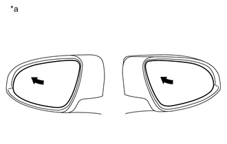
*a Turn to Fully Left Position Turn the ignition switch to ON.
-
Using the outer mirror switch assembly, turn the mirror surface to the fully left position.
-
Press the M1 switch while the SET switch is being pressed.
-
Check that the buzzer sounds for 0.5 seconds and the mirror surface position is memorized.
-
Using the outer mirror switch assembly, turn the mirror surface to the fully right position.
-
Press the M1 switch.
-
Check that the buzzer sounds for 0.1 seconds and the outer mirror automatically moves to the memorized fully left position.
Result Result Proceed to Memory and reactivation functions on both mirrors are not normal A Memory and reactivation functions on driver door mirror are not normal B Memory and reactivation functions on front passenger door mirror are not normal C
A
REPLACE MAIN BODY ECU (MULTIPLEX NETWORK BODY ECU) Click here
C
REPLACE OUTER REAR VIEW MIRROR ASSEMBLY (FRONT PASSENGER DOOR) Click here
B
-
-
REPLACE OUTER REAR VIEW MIRROR ASSEMBLY (DRIVER DOOR)
-
Temporarily replace the outer rear view mirror assembly (driver door) with a new or known good one.
Result Proceed to NEXT
NEXT
-
-
CHECK MEMORY AND REACTIVATION FUNCTION
-
*a Turn to Fully Left Position Turn the ignition switch to ON.
-
Using the outer mirror switch assembly, turn the mirror surface to the fully left position.
-
Press the M1 switch while the SET switch is being pressed.
-
Check that the buzzer sounds for 0.5 seconds and the mirror surface position is memorized.
-
Using the outer mirror switch assembly, turn the mirror surface to the fully right position.
-
Press the M1 switch.
-
Check that the buzzer sounds for 0.1 seconds and the outer mirror automatically moves to the memorized fully left position.
Result Proceed to OK NG
OK
END (OUTER REAR VIEW MIRROR ASSEMBLY (DRIVER DOOR) WAS DEFECTIVE)
NG
REPLACE OUTER MIRROR CONTROL ECU ASSEMBLY (DRIVER DOOR) Click here
-
-
REPLACE OUTER REAR VIEW MIRROR ASSEMBLY (FRONT PASSENGER DOOR)
-
Temporarily replace the outer rear view mirror assembly (front passenger door) with a new or known good one.
Result Proceed to NEXT
NEXT
-
-
CHECK MEMORY AND REACTIVATION FUNCTION
-
*a Turn to Fully Left Position Turn the ignition switch to ON.
-
Using the outer mirror switch assembly, turn the mirror surface to the fully left position.
-
Press the M1 switch while the SET switch is being pressed.
-
Check that the buzzer sounds for 0.5 seconds and the mirror surface position is memorized.
-
Using the outer mirror switch assembly, turn the mirror surface to the fully right position.
-
Press the M1 switch.
-
Check that the buzzer sounds for 0.1 seconds and the outer mirror automatically moves to the memorized fully left position.
Result Proceed to OK NG
OK
END (OUTER REAR VIEW MIRROR ASSEMBLY (FRONT PASSENGER DOOR) WAS DEFECTIVE)
NG
REPLACE OUTER MIRROR CONTROL ECU ASSEMBLY (FRONT PASSENGER DOOR) Click here
-
-
INSPECT SEAT MEMORY SWITCH
-
Remove the seat memory switch (driver door).
-
Inspect the seat memory switch (driver door).
Result Proceed to OK NG
NG
REPLACE SEAT MEMORY SWITCH Click here
OK
-
-
CHECK HARNESS AND CONNECTOR (SEAT MEMORY SWITCH - OUTER MIRROR CONTROL ECU ASSEMBLY (DRIVER DOOR) - BODY GROUND)
-
Disconnect the I2*1 or H2*2 outer mirror control ECU assembly (driver door) connector.
-
*1: for LHD
-
*2: for RHD
-
-
Disconnect the I11 seat memory switch connector.
-
Measure the resistance according to the value(s) in the table below.
Standard Resistance for LHD Tester Connection Condition Specified Condition I2-1 (MM) - I11-8 (MMRY) Always Below 1 Ω I2-2 (M1) - I11-4 (1) Always Below 1 Ω I2-3 (M2) - I11-3 (2) Always Below 1 Ω I11-2 (E) - Body ground Always Below 1 Ω I2-1 (MM) or I11-8 (MMRY) - Body ground Always 10 kΩ or higher I2-2 (M1) or I11-4 (1) - Body ground Always 10 kΩ or higher I2-3 (M2) or I11-3 (2) - Body ground Always 10 kΩ or higher for RHD Tester Connection Condition Specified Condition H2-1 (MM) - H12-8 (MRY) Always Below 1 Ω H2-2 (M1) - H12-4 (M1) Always Below 1 Ω H2-3 (M2) - H12-3 (M2) Always Below 1 Ω H12-2 (E) - Body ground Always Below 1 Ω H2-1 (MM) or H12-8 (MRY) - Body ground Always 10 kΩ or higher H2-2 (M1) or H12-4 (M1) - Body ground Always 10 kΩ or higher H2-3 (M2) or H12-3 (M2) - Body ground Always 10 kΩ or higher Result Proceed to OK NG
OK
REPLACE OUTER MIRROR CONTROL ECU ASSEMBLY (DRIVER DOOR) Click here
NG
REPAIR OR REPLACE HARNESS OR CONNECTOR
-