POWER MIRROR CONTROL SYSTEM(w/ Memory) AUTO Power Retract Mirrors do not operate
DESCRIPTION
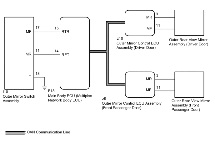
The outer mirror switch assembly sends the auto retractable outer mirror switch signal to the main body ECU (multiplex network body ECU). The main body ECU (multiplex network body ECU) sends the auto retract/return signal to the outer mirror control ECU assemblies via CAN communication, which then controls the mirrors.
When the outer mirror control ECU assemblies receive a door lock output signal from the main body ECU (multiplex network body ECU) while the auto retractable outer mirror switch is on, the outer mirror control ECU assemblies operate the retract motors built into the outer rear view mirror assemblies to retract or return the outer rear view mirror assemblies.
WIRING DIAGRAM
CAUTION / NOTICE / HINT
Note
-
The power mirror control system (w/ Memory) uses the CAN communication system. Inspect the communication function by following How to Proceed with Troubleshooting. Troubleshoot the power mirror control system (w/ Memory) after confirming that the communication systems are functioning properly.
-
Before replacing the main body ECU (multiplex network body ECU), refer to Service Bulletin.
-
As the door control battery is installed between the vehicle battery and main body ECU (multiplex network body ECU), first perform the inspections in On-Vehicle Inspection to confirm that there are no malfunctions in the power source circuit for the main body ECU (multiplex network body ECU) before performing this troubleshooting procedure.*
-
*: for LHD
PROCEDURE
-
CHECK POWER RETRACT MIRROR FUNCTION
-
Check the power retract mirror function.
OK Power retract mirror function operates normally. Result Proceed to OK NG
NG 
GO TO OTHER DIAGNOSIS PROCEDURE (Power Retractable Mirrors do not Operate with Power Retract Mirror Switch) Click here
OK 
-
-
CHECK POWER DOOR LOCK CONTROL SYSTEM
-
Check the power door lock control system.
OK Power door lock control system is normal. Result Proceed to OK NG
NG
GO TO POWER DOOR LOCK CONTROL SYSTEM Click here
OK
-
-
CHECK WIRELESS DOOR LOCK CONTROL SYSTEM
-
Check the wireless door lock control system.
OK Wireless door lock control system is normal. Result Proceed to OK NG
NG
GO TO WIRELESS DOOR LOCK CONTROL SYSTEM Click here
OK
-
-
CHECK SMART ENTRY AND START SYSTEM (for Entry Function)
-
Check the smart entry and start system (for Entry Function).
OK Smart entry and start system (for Entry Function) is normal. Result Proceed to OK NG
NG
GO TO SMART ENTRY AND START SYSTEM (for Entry Function) Click here
OK
-
-
READ VALUE USING GTS
-
Connect the GTS to the DLC3.
-
Turn the ignition switch to ON.
-
Turn the GTS on.
-
Enter the following menus: Body Electrical / Main Body / Data List.
-
Read the Data List according to the display on the GTS.
Body Electrical > Main Body > Data ListTester Display Measurement Item Range Normal Condition Diagnostic Note Auto Mirror SW Auto retractable outer mirror switch signal OFF or ON OFF: Auto retractable outer mirror switch off
ON: Auto retractable outer mirror switch on
-
Body Electrical > Main Body > Data ListTester Display Auto Mirror SW OK On the GTS screen, ON or OFF is displayed accordingly. Result Proceed to OK NG
NG 
INSPECT OUTER MIRROR SWITCH ASSEMBLY Click here
OK
-
-
REPLACE OUTER MIRROR CONTROL ECU ASSEMBLY
-
Replace the outer mirror control ECU assembly.
Result Proceed to OK NG
OK
END (OUTER MIRROR CONTROL ECU ASSEMBLY WAS DEFECTIVE)
NG
REPLACE MAIN BODY ECU (MULTIPLEX NETWORK BODY ECU) Click here
-
-
INSPECT OUTER MIRROR SWITCH ASSEMBLY
-
Remove the outer mirror switch assembly.
-
Inspect the outer mirror switch assembly.
Result Proceed to OK NG
NG
REPLACE OUTER MIRROR SWITCH ASSEMBLY Click here
OK
-
-
CHECK HARNESS AND CONNECTOR (OUTER MIRROR SWITCH ASSEMBLY - MAIN BODY ECU (MULTIPLEX NETWORK BODY ECU))
-
Disconnect the I10 outer mirror switch assembly.
-
Disconnect the F18 main body ECU (multiplex network body ECU).
-
Measure the resistance according to the value(s) in the table below.
Standard Resistance Tester Connection Condition Specified Condition I10-17 (MF) - F18-15 (RTR) Always Below 1 Ω I10-17 (MF) or F18-15 (RTR) - Body ground Always 10 kΩ or higher Result Proceed to OK NG
OK
REPLACE MAIN BODY ECU (MULTIPLEX NETWORK BODY ECU) Click here
NG
REPAIR OR REPLACE HARNESS OR CONNECTOR
-