POWER BACK DOOR SYSTEM Power Back Door cannot be Opened or Closed Using the Power Back Door Switch
DESCRIPTION
When the back door cannot be opened or closed using the rear door control switch, one of the following may be malfunctioning: 1) rear door control switch circuit, 2) multiplex network door ECU or 3) main body ECU (multiplex network body ECU).
WIRING DIAGRAM
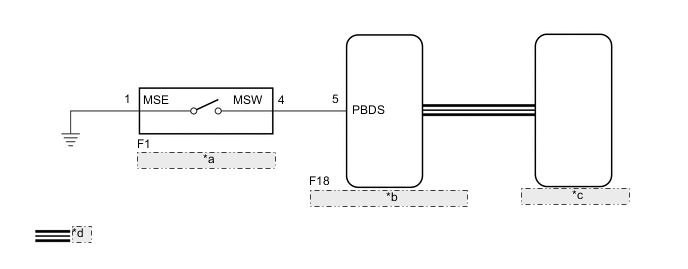
| *a | Rear Door Control Switch |
| *b | Main Body ECU (Multiplex Network Body ECU) |
| *c | Multiplex Network Door ECU |
| *d | CAN Communication Line |
CAUTION / NOTICE / HINT
Note
-
Inspect the communication function by following How to Proceed with Troubleshooting. Troubleshoot the power back door system after confirming that the communication system is functioning properly.
-
If the main body ECU (multiplex network body ECU) is replaced, refer to Service Bulletin.
-
As the door control battery is installed between the vehicle battery and main body ECU (multiplex network body ECU), first perform the inspections in On-Vehicle Inspection to confirm that there are no malfunctions in the power source circuit for the main body ECU (multiplex network body ECU) before performing this troubleshooting procedure.*
-
*: for LHD
PROCEDURE
-
READ VALUE USING GTS
-
Connect the GTS to the DLC3.
-
Turn the engine switch on (IG).
-
Turn the GTS on.
-
Enter the following menus: Body Electrical / Main Body / Data List.
-
Read the Data List according to the display on the GTS.
Body Electrical > Main Body > Data ListTester Display Measurement Item Range Normal Condition Diagnostic Note Back Door Open SW Rear door control switch signal ON or OFF ON: Rear door control switch on
OFF: Rear door control switch off
-
Body Electrical > Main Body > Data ListTester Display Back Door Open SW OK On the GTS screen, ON or OFF is displayed accordingly. Result Proceed to OK NG
NG 
INSPECT REAR DOOR CONTROL SWITCH Click here
OK 
-
-
REPLACE MULTIPLEX NETWORK DOOR ECU
-
Temporarily replace the multiplex network door ECU with a new or known good one.
Result Proceed to NEXT
NEXT
-
-
INITIALIZE MULTIPLEX NETWORK DOOR ECU
-
Perform the initialization for the multiplex network door ECU.
Result Proceed to NEXT
NEXT
-
-
CHECK POWER BACK DOOR SYSTEM
-
Check that the power back door system operates normally.
Result Result Proceed to Power back door system operates normally A Power back door system does not operate B
A 
END (MULTIPLEX NETWORK DOOR ECU WAS DEFECTIVE)
B
REPLACE MAIN BODY ECU (MULTIPLEX NETWORK BODY ECU) Click here
-
-
INSPECT REAR DOOR CONTROL SWITCH
-
Remove the rear door control switch.
-
Inspect the rear door control switch.
Result Proceed to OK NG
NG
REPLACE REAR DOOR CONTROL SWITCH Click here
OK
-
-
CHECK HARNESS AND CONNECTOR (REAR DOOR CONTROL SWITCH - MAIN BODY ECU (MULTIPLEX NETWORK BODY ECU) AND BODY GROUND)
-
Disconnect the F1 rear door control switch connector.
-
Disconnect the F18 main body ECU (multiplex network body ECU) connector.
-
Measure the resistance according to the value(s) in the table below.
Standard Resistance Tester Connection Condition Specified Condition F1-4 (MSW) - F18-5 (PBDS) Always Below 1 Ω F1-1 (MSE) - Body ground Always Below 1 Ω F1-4 (MSW) or F18-5 (PBDS) - Body ground Always 10 kΩ or higher Result Proceed to OK NG
OK
REPLACE MAIN BODY ECU (MULTIPLEX NETWORK BODY ECU) Click here
NG
REPAIR OR REPLACE HARNESS OR CONNECTOR
-