POWER BACK DOOR SYSTEM, Diagnostic DTC:B222B
| DTC Code | DTC Name |
|---|---|
| B222B | PBD Touch Sensor RH Circuit |
DESCRIPTION
This DTC is stored when the multiplex network door ECU detects a malfunction of the power back door sensor assembly RH touch sensor.
| DTC No. | Detection Item | DTC Detection Condition | Trouble Area |
|---|---|---|---|
| B222B | PBD Touch Sensor RH Circuit | The multiplex network door ECU detects a malfunction of the power back door sensor assembly RH touch sensor. |
|
WIRING DIAGRAM
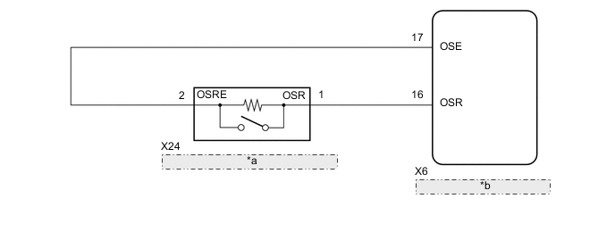
| *a | Power Back Door Sensor Assembly RH |
| *b | Multiplex Network Door ECU |
PROCEDURE
-
CHECK FOR DTC
-
Clear the DTCs.
Body Electrical > Back Door > Clear DTCs -
Check for DTCs.
Body Electrical > Back Door > Trouble CodesResult Result Proceed to DTC B222B is not output A DTC B222B is output B
A 
USE SIMULATION METHOD TO CHECK Click here
B 
-
-
READ VALUE USING GTS
-
Connect the GTS to the DLC3.
-
Turn the engine switch on (IG).
-
Turn the GTS on.
-
Enter the following menus: Body Electrical / Back Door / Data List.
-
Read the Data List according to the display on the GTS.
Body Electrical > Back Door > Data ListTester Display Measurement Item Range Normal Condition Diagnostic Note PBD Touch Sensor (Right) Power back door sensor assembly RH signal ON, OFF or Open ON: Power back door sensor assembly RH pressed
OFF: Power back door sensor assembly RH not pressed
Open: Power back door sensor assembly RH circuit open
-
Body Electrical > Back Door > Data ListTester Display PBD Touch Sensor (Right) Result Result Proceed to On the GTS screen, ON or OFF is displayed accordingly A On the GTS screen, ON or OFF is not displayed accordingly, or Open is displayed for power back door sensor assembly RH B
A
REPLACE MULTIPLEX NETWORK DOOR ECU Click here
B
-
-
INSPECT POWER BACK DOOR SENSOR ASSEMBLY RH
-
Remove the power back door sensor assembly RH.
-
Inspect the power back door sensor assembly RH.
Result Proceed to OK NG
NG
REPLACE POWER BACK DOOR SENSOR ASSEMBLY RH Click here
OK
-
-
CHECK HARNESS AND CONNECTOR (MULTIPLEX NETWORK DOOR ECU - POWER BACK DOOR SENSOR ASSEMBLY RH)
-
Disconnect the X6 multiplex network door ECU connector.
-
Disconnect the X24 power back door sensor assembly RH connector.
-
Measure the resistance according to the value(s) in the table below.
Standard Resistance Tester Connection Condition Specified Condition X6-16 (OSR) - X24-1 (OSR) Always Below 1 Ω X6-17 (OSE) - X24-2 (OSRE) Always Below 1 Ω X6-16 (OSR) or X24-1 (OSR) - Body ground Always 10 kΩ or higher X6-17 (OSE) or X24-2 (OSRE) - Body ground Always 10 kΩ or higher Result Proceed to OK NG
OK
REPLACE MULTIPLEX NETWORK DOOR ECU Click here
NG
REPAIR OR REPLACE HARNESS OR CONNECTOR
-