BACK DOOR CLOSER SYSTEM Back Door Closer does not Operate
DESCRIPTION
When the back door closer system does not operate, one of the following may be the cause: 1) improper fit of the back door or a foreign object stuck in the back door, 2) the multiplex network door ECU has not been initialized, 3) a malfunction in the multiplex network door ECU power source circuit, 4) a malfunction in the back door lock assembly circuit, or 5) a multiplex network door ECU malfunction.
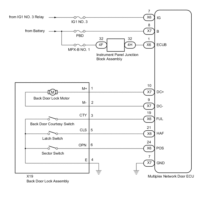
WIRING DIAGRAM
CAUTION / NOTICE / HINT
Note
Inspect the fuses for circuits related to this system before performing the following procedure.
PROCEDURE
-
CHECK FOR DTC
-
Check for DTCs.
Body Electrical > Back Door > Trouble CodesResult Result Proceed to DTCs are not output A DTC B2250 is output B DTC B2251 is output C
B 
GO TO DTC CHART Click here
C
GO TO DTC CHART Click here
A 
-
-
CHECK BACK DOOR LOCK FUNCTION
-
Check if the back door can be fully closed by hand.
Result Result Proceed to The back door can be closed normally A The back door cannot be closed normally B
B
IMPROPER FIT OF BACK DOOR, OR A FOREIGN OBJECT IS STUCK IN BACK DOOR
A
-
-
INITIALIZE MULTIPLEX NETWORK DOOR ECU
-
Perform the initialization of the multiplex network door ECU.
Result Proceed to NEXT
NEXT
-
-
CHECK BACK DOOR CLOSER SYSTEM
-
Check the back door closer system operation.
Result Result Proceed to The back door closer system operates normally A The back door closer system operates not normally B
A
END (BACK DOOR CLOSER SYSTEM HAS NOT BEEN INITIALIZED)
B
-
-
CHECK HARNESS AND CONNECTOR (MULTIPLEX NETWORK DOOR ECU - BATTERY AND BODY GROUND)
-
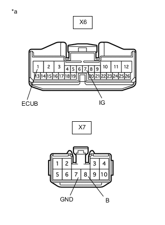
*a Front view of wire harness connector
(to Multiplex Network Door ECU)
Disconnect the X6 and X7 multiplex network door ECU connectors.
-
Measure the resistance according to the value(s) in the table below.
Standard Resistance Tester Connection Condition Specified Condition X7-7 (GND) - Body ground Always Below 1 Ω -
Measure the voltage according to the value(s) in the table below.
Standard Voltage Tester Connection Condition Specified Condition X6-1 (ECUB) - Body ground Always 11 to 14 V X7-8 (B) - Body ground Always 11 to 14 V X6-7 (IG) - Body ground Engine switch on (IG) 11 to 14 V X6-7 (IG) - Body ground Engine switch off Below 1 V Result Proceed to OK NG
NG
REPAIR OR REPLACE HARNESS OR CONNECTOR
OK
-
-
INSPECT BACK DOOR LOCK ASSEMBLY
-
Remove the back door lock assembly.
-
Inspect the back door lock assembly.
Result Proceed to OK NG
NG
REPLACE BACK DOOR LOCK ASSEMBLY Click here
OK
-
-
CHECK HARNESS AND CONNECTOR (BACK DOOR LOCK ASSEMBLY - MULTIPLEX NETWORK DOOR ECU AND BODY GROUND)
-
Disconnect the X19 back door lock assembly connector.
-
Disconnect the X6 and X7 multiplex network door ECU connectors.
-
Measure the resistance according to the value(s) in the table below.
Standard Resistance Tester Connection Condition Specified Condition X19-1 (M+) - X7-10 (DC+) Always Below 1 Ω X19-2 (M-) - X7-9 (DC-) Always Below 1 Ω X19-3 (CTY) - X6-19 (FUL) Always Below 1 Ω X19-5 (CLS) - X6-21 (HAF) Always Below 1 Ω X19-6 (OPN) - X6-24 (POS) Always Below 1 Ω X19-4 (E) - Body ground Always Below 1 Ω X19-1 (M+) or X7-10 (DC+) - Body ground Always 10 kΩ or higher X19-2 (M-) or X7-9 (DC-) - Body ground Always 10 kΩ or higher X19-3 (CTY) or X6-19 (FUL) - Body ground Always 10 kΩ or higher X19-5 (CLS) or X6-21 (HAF) - Body ground Always 10 kΩ or higher X19-6 (OPN) or X6-24 (POS) - Body ground Always 10 kΩ or higher Result Proceed to OK NG
OK
REPLACE MULTIPLEX NETWORK DOOR ECU Click here
NG
REPAIR OR REPLACE HARNESS OR CONNECTOR
-