BACK DOOR CLOSER SYSTEM TERMINALS OF ECU
-
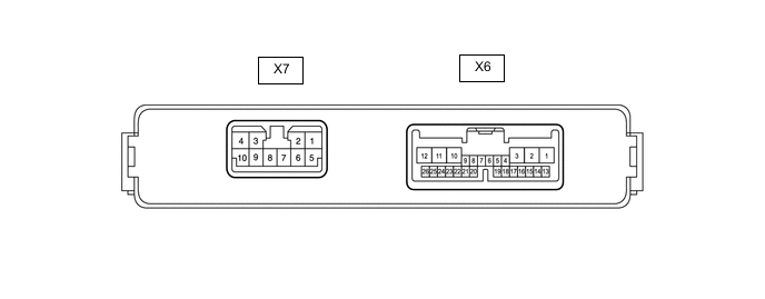
CHECK MULTIPLEX NETWORK DOOR ECU
-
Disconnect the X6 and X7 multiplex network door ECU connectors.
-
Measure the voltage and resistance according to the value(s) in the table below.
Terminal No. (Symbol) Wiring Color Terminal Description Condition Specified Condition X6-1 (ECUB) - Body ground BE - Body ground Battery power supply Always 11 to 14 V X6-7 (IG) - Body ground Y - Body ground IG power supply Engine switch on (IG) 11 to 14 V X6-7 (IG) - Body ground Y - Body ground IG power supply Engine switch off Below 1 V X7-8 (B) - Body ground G - Body ground Battery power supply Always 11 to 14 V X7-7 (GND) - Body ground W-B - Body ground Body ground Always Below 1 Ω -
Reconnect the X6 and X7 multiplex network door ECU connectors.
-
Measure the voltage according to the value(s) in the table below.
Terminal No. (Symbol) Wiring Color Terminal Description Condition Specified Condition X7-10 (DC+) - X7-9 (DC-) LA-V - LA-W Back door lock assembly (back door lock motor) circuit Back door lock motor operating 11 to 14 V X7-10 (DC+) - X7-9 (DC-) LA-V - LA-W Back door lock assembly (back door lock motor) circuit Back door lock motor not operating Below 1 V X6-19 (FUL) - Body ground L - Body ground Back door lock assembly (back door courtesy switch) signal circuit Back door closed → open 11 to 14 V → Below 1 V X6-21 (HAF) - Body ground BE - Body ground Back door lock assembly (latch switch) signal circuit Back door closed → fully open 11 to 14 V → Below 1 V X6-24 (POS) - Body ground GR - Body ground Back door lock assembly (sector switch) signal circuit Back door open → Back door closer operating → Back door closed Below 1 V → 11 to 14 V → Below 1 V
-
-
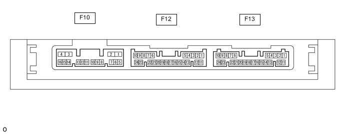
CHECK CERTIFICATION ECU (SMART KEY ECU ASSEMBLY)
-
Disconnect the F10 and F13 certification ECU (smart key ECU assembly) connectors.
-
Measure the voltage and resistance according to the value(s) in the table below.
Terminal No. (Symbol) Wiring Color Terminal Description Condition Specified Condition F13-10 (+B) - Body ground GR - Body ground Battery power supply Always 11 to 14 V F10-4 (CUTB) - Body ground BE - Body ground Battery power supply Always 11 to 14 V F13-11 (E) - Body ground W-B - Body ground Body ground Always Below 1 Ω -
Reconnect the F10 and F13 certification ECU (smart key ECU assembly) connectors.
-
Measure the voltage according to the value(s) in the table below.
Terminal No. (Symbol) Wiring Color Terminal Description Condition Specified Condition F10-3 (IG1D) - Body ground G - Body ground IG power supply Engine switch on (IG) 11 to 14 V F10-3 (IG1D) - Body ground G - Body ground IG power supply Engine switch off Below 1 V F12-5 (TSW5) - Body ground R - Body ground Back door opener switch assembly signal Back door opener switch assembly off Pulse generation F12-5 (TSW5) - Body ground R - Body ground Back door opener switch assembly signal Back door opener switch assembly on Below 1 V
-