GLASS HATCH OPENER SYSTEM Glass Hatch Opener System does not Operate
DESCRIPTION
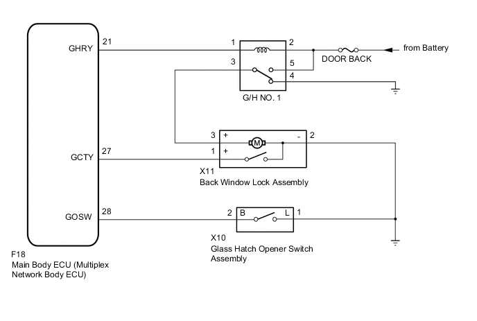
The glass hatch opener system enables the back door glass to be opened when the glass hatch opener switch assembly is pressed.
WIRING DIAGRAM
CAUTION / NOTICE / HINT
Note
-
Inspect the fuses for circuits related to this system before performing the following procedure.
-
If the main body ECU (multiplex network body ECU) is replaced, refer to Service Bulletin.*
*: w/ Smart Entry and Start System
-
As the door control battery is installed between the vehicle battery and main body ECU (multiplex network body ECU), first perform the inspections in On-Vehicle Inspection to confirm that there are no malfunctions in the power source circuit for the main body ECU (multiplex network body ECU) before performing this troubleshooting procedure.*
*: for LHD
PROCEDURE
-
CONFIRM MODEL
-
Choose the model to be inspected.
Result Result Proceed to w/ Smart Entry and Start System A w/o Smart Entry and Start System B
B 
GO TO STEP 3 Click here
A 
-
-
CHECK SMART ENTRY AND START SYSTEM (for Entry Function)
-
Check if the entry glass hatch open function operates normally.
OK Entry glass hatch open function operates normally. Result Proceed to OK NG
NG 
GO TO SMART ENTRY AND START SYSTEM (for Entry Function) Click here
OK
-
-
READ VALUE USING GTS
-
Connect the GTS to the DLC3.
-
Turn the ignition switch to ON.
-
Turn the GTS on.
-
Enter the following menus: Body Electrical / Main Body / Data List.
-
Read the Data List according to the display on the GTS.
Body Electrical > Main Body > Data ListTester Display Measurement Item Range Normal Condition Diagnostic Note Glass Hatch Courtesy Switch Back window courtesy switch signal OFF or ON OFF: Back door glass closed
ON: Back door glass open
-
Body Electrical > Main Body > Data ListTester Display Glass Hatch Courtesy Switch OK The GTS display changes correctly in response to the opening and closing operation of the back door glass. Result Proceed to OK NG
NG
GO TO LIGHTING SYSTEM (Proceed to Back Door Courtesy Switch Circuit) Click here
OK
-
-
READ VALUE USING GTS
-
Enter the following menus: Body Electrical / Main Body / Data List.
-
Read the Data List according to the display on the GTS.
Body Electrical > Main Body > Data ListTester Display Measurement Item Range Normal Condition Diagnostic Note Glass Hatch Opener Switch Glass hatch opener switch signal OFF or ON OFF: Glass hatch opener switch not operated
ON: Glass hatch opener switch operated
-
Body Electrical > Main Body > Data ListTester Display Glass Hatch Opener Switch OK The GTS display changes correctly in response to the operation of the glass hatch opener switch. Result Proceed to OK NG
NG
CHECK HARNESS AND CONNECTOR (GLASS HATCH OPENER SWITCH ASSEMBLY - MAIN BODY ECU (MULTIPLEX NETWORK BODY ECU) AND BODY GROUND) Click here
OK
-
-
PERFORM ACTIVE TEST USING GTS
-
Enter the following menus: Body Electrical / Main Body / Active Test.
-
Perform the Active Test according to the display on the GTS.
Body Electrical > Main Body > Active TestTester Display Measurement Item Control Range Diagnostic Note Glass Hatch Open Operate Glass Hatch OFF or ON -
Body Electrical > Main Body > Active TestTester Display Glass Hatch Open OK The glass hatch opens. Result Proceed to OK NG
OK
REPLACE MAIN BODY ECU (MULTIPLEX NETWORK BODY ECU) Click here
NG
-
-
INSPECT G/H NO. 1 RELAY
-
Inspect the G/H No. 1 relay.
Result Proceed to OK NG
NG
REPLACE G/H NO. 1 RELAY
OK
-
-
CHECK HARNESS AND CONNECTOR (G/H NO. 1 RELAY - BATTERY)
-
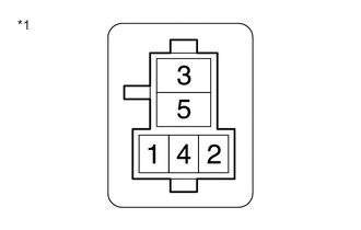
*1 G/H No. 1 Relay Holder Measure the voltage according to the value(s) in the table below.
Standard Voltage Tester Connection Condition Specified Condition G/H No. 1 relay holder terminal 2 - Body ground Always 11 to 14 V G/H No. 1 relay holder terminal 5 - Body ground Always 11 to 14 V Result Proceed to OK NG
NG
REPAIR OR REPLACE HARNESS OR CONNECTOR
OK
-
-
CHECK HARNESS AND CONNECTOR (G/H NO. 1 RELAY - MAIN BODY ECU (MULTIPLEX NETWORK BODY ECU))
-
*1 G/H No. 1 Relay Holder Disconnect the F18 main body ECU (multiplex network body ECU) connector.
-
Measure the resistance according to the value(s) in the table below.
Standard Resistance Tester Connection Condition Specified Condition G/H No. 1 relay holder terminal 1 - F18-21 (GHRY) Always Below 1 Ω G/H No. 1 relay holder terminal 1 or F18-21 (GHRY) - Body ground Always 10 kΩ or higher Result Proceed to OK NG
NG
REPAIR OR REPLACE HARNESS OR CONNECTOR
OK
-
-
INSPECT BACK WINDOW LOCK ASSEMBLY
-
Remove the back window lock assembly.
-
Inspect the back window lock assembly.
Result Proceed to OK NG
NG
REPLACE BACK WINDOW LOCK ASSEMBLY Click here
OK
-
-
CHECK HARNESS AND CONNECTOR (BACK WINDOW LOCK ASSEMBLY - G/H NO. 1 RELAY AND BODY GROUND)
-
*1 G/H No. 1 Relay Holder Disconnect the X11 back window lock assembly connector.
-
Measure the resistance according to the value(s) in the table below.
Standard Resistance Tester Connection Condition Specified Condition X11-3 (+) - G/H No. 1 relay holder terminal 3 Always Below 1 Ω X11-3 (+) or G/H No. 1 relay holder terminal 3 - Body ground Always 10 kΩ or higher X11-2 (-) - Body ground Always Below 1 Ω Result Proceed to OK NG
OK
REPLACE MAIN BODY ECU (MULTIPLEX NETWORK BODY ECU) Click here
NG
REPAIR OR REPLACE HARNESS OR CONNECTOR
-
-
CHECK HARNESS AND CONNECTOR (GLASS HATCH OPENER SWITCH ASSEMBLY - MAIN BODY ECU (MULTIPLEX NETWORK BODY ECU) AND BODY GROUND)
-
Disconnect the X10 glass hatch opener switch assembly connector.
-
Disconnect the F18 main body ECU (multiplex network body ECU) connector.
-
Measure the resistance according to the value(s) in the table below.
Standard Resistance Tester Connection Condition Specified Condition X10-2 (B) - F18-28 (GOSW) Always Below 1 Ω X10-2 (B) or F18-28 (GOSW) - Body ground Always 10 kΩ or higher X10-1 (L) - Body ground Always Below 1 Ω Result Proceed to OK NG
NG
REPAIR OR REPLACE HARNESS OR CONNECTOR
OK
-
-
INSPECT GLASS HATCH OPENER SWITCH ASSEMBLY
-
Remove the glass hatch opener switch assembly.
-
Inspect the glass hatch opener switch assembly.
Result Proceed to OK NG
OK
REPLACE MAIN BODY ECU (MULTIPLEX NETWORK BODY ECU) Click here
NG
REPLACE GLASS HATCH OPENER SWITCH ASSEMBLY Click here
-