ROOF HEADLINING REASSEMBLY
PROCEDURE
-
INSTALL NO. 1 ROOF WIRE (for Normal Roof)
-
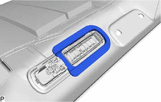
Apply butyl tape as shown in the illustration.
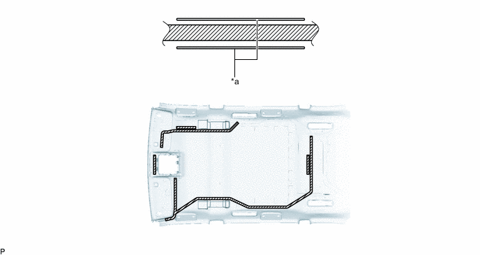
*a Marking - - 
Butyl Tape - - Note
Securely attach butyl tape.
-
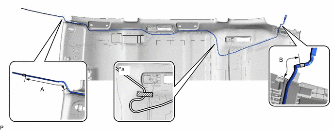
Engage each clamp.
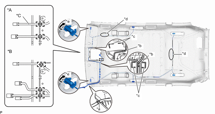
*A w/o Pre-collision System *B w/ Pre-collision System *C w/ Rain Sensor - - *a Marking Tape (A) *b Marking Tape (B) *c Marking *d Adjustment Area *e 45° - - -
Turn the 2 visor connectors clockwise approximately 45° to install them to the roof headlining assembly.
-
Align the marking tape (A) on the No. 1 roof wire with the vehicle front side tab of the roof headlining assembly.
-
Align the edge of the 2 marking tapes (B) on the No. 1 roof wire with the markings on the roof headlining assembly.
-
Attach the No. 1 roof wire with the butyl tape.
Note
-
Securely attach the No. 1 roof wire.
-
If any of the No. 1 roof wire is left loose, it will cause an abnormal noise.
-
Make sure to attach the No. 1 roof wire without leaving any of it loose.
Tech Tips
Secure the extra length of the No. 1 roof wire in the adjustment area.
-
-
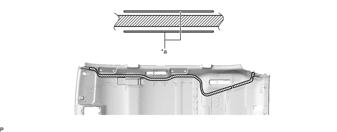
Install the No. 1 roof wire to the roof headlining assembly with adhesive tape.
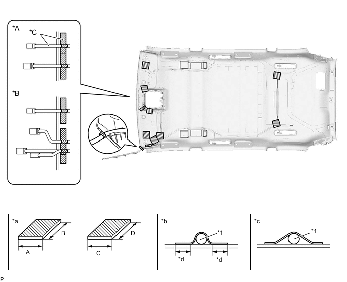
*A w/o Pre-collision System *B w/ Pre-collision System *C w/ Rain Sensor - - *1 No. 1 Roof Wire - - *a Adhesive Tape Size *b Correct *c Incorrect *d 15 mm (0.591 in.) or more Adhesive Tape - - Adhesive Tape Size Area Dimension A 20 mm (0.787 in.) B 80 mm (3.15 in.) or more C 80 mm (3.15 in.) D 80 mm (3.15 in.) Note
-
Apply the tape securely in place.
-
Do not touch the adhesive surface when applying the tape to prevent adhesion failure.
-
-
-
INSTALL NO. 1 ROOF WIRE (for Sliding Roof)
-
Apply butyl tape as shown in the illustration.
*A w/ Rear Seat Entertainment System - - *a Marking - - Butyl Tape - - Note
Securely attach butyl tape.
-
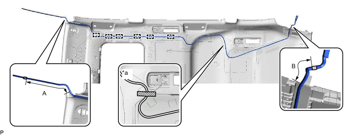
Engage each clamp.
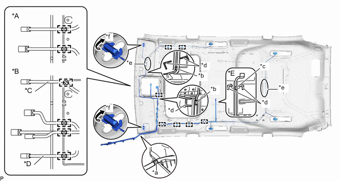
*A w/o Pre-collision System *B w/ Pre-collision System *C for LHD with Rain Sensor *D for RHD with Rain Sensor *E w/ Rear Seat Entertainment System - - *a Marking Tape (A) *b Marking Tape (B) *c Marking Tape (C) *d Marking *e Adjustment Area *f 45° -
Turn the 2 visor connectors clockwise approximately 45° to install them to the roof headlining assembly.
-
Align the marking tape (A) on the No. 1 roof wire with the vehicle front side tab of the roof headlining assembly.
-
Align the edge of the 2 marking tapes (B) on the No. 1 roof wire with the markings on the roof headlining assembly.
-
w/ Rear Seat Entertainment System:
-
Align the edge of the marking tape (C) on the No. 1 roof wire with the markings on the roof headlining assembly.
-
-
Attach the No. 1 roof wire with the butyl tape.
Note
-
Securely attach the No. 1 roof wire.
-
If any of the No. 1 roof wire is left loose, it will cause an abnormal noise.
-
Make sure to attach the No. 1 roof wire without leaving any of it loose.
Tech Tips
Secure the extra length of the No. 1 roof wire in the adjustment area.
-
-
Install the No. 1 roof wire to the roof headlining assembly with adhesive tape.
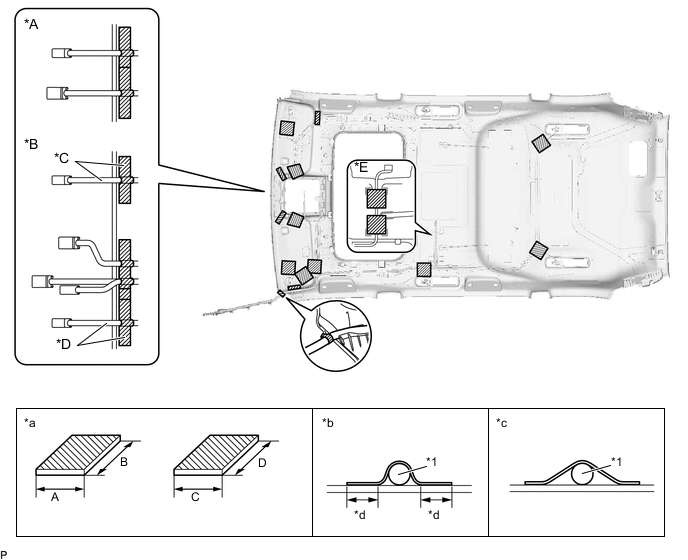
*A w/o Pre-collision System *B w/ Pre-collision System *C for LHD with Rain Sensor *D for RHD with Rain Sensor *E w/ Rear Seat Entertainment System - - *1 No. 1 Roof Wire - - *a Adhesive Tape Size *b Correct *c Incorrect *d 15 mm (0.591 in.) or more Adhesive Tape - - Adhesive Tape Size Area Dimension A 20 mm (0.787 in.) B 80 mm (3.15 in.) or more C 80 mm (3.15 in.) D 80 mm (3.15 in.) Note
-
Apply the tape securely in place.
-
Do not touch the adhesive surface when applying the tape to prevent adhesion failure.
-
-
-
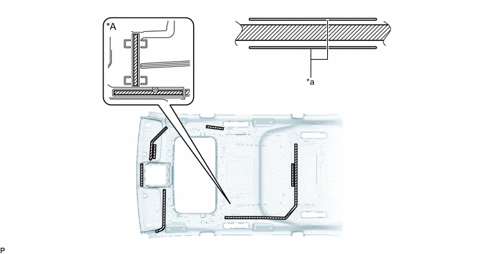
INSTALL ROOF HEADLINING SUPPORT PLATE (for Normal Roof)
-
Remove the release paper from 2 new roof headlining support plates.
Tech Tips
After removing the release paper, keep the exposed adhesive free from foreign matter.
-
Install the 2 roof headlining support plates as shown in the illustration.
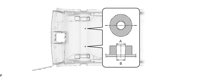
Standard Measurement Area Dimension A 14 mm (0.551 in.) B 11 mm (0.433 in.)
-
-
INSTALL ROOF HEADLINING SUPPORT PLATE (for Sliding Roof)
-
Remove the release paper from 2 new roof headlining support plates.
Tech Tips
After removing the release paper, keep the exposed adhesive free from foreign matter.
-
Install the 2 roof headlining support plates as shown in the illustration.
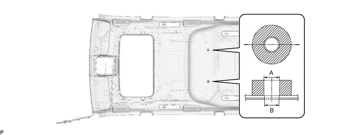
Standard Measurement Area Dimension A 14 mm (0.551 in.) B 11 mm (0.433 in.)
-
-
INSTALL SPOT LIGHT ASSEMBLY LH
Tech Tips
Use the same procedure for the front side and rear side.
-
INSTALL SPOT LIGHT ASSEMBLY RH
Tech Tips
Use the same procedure as for the LH side.
-
INSTALL AIR DUCT SEAL
Tech Tips
Use the same procedure for all air duct seals.
-
Remove the release paper from a new air duct seal.
Tech Tips
After removing the release paper, keep the exposed adhesive free from foreign matter.
-
Install the air duct seal as shown in the illustration.
-
-
INSTALL REAR WASHER HOSE ASSEMBLY (for Normal Roof)
-
Apply butyl tape as shown in the illustration.

*a Marking - - Butyl Tape - - Note
Securely attach butyl tape.
-
Align the edge of the marking tape on the rear washer hose assembly from the vehicle front side tab of the roof headlining assembly as shown in the illustration.
*a Adjustment Area - - 
Marking Tape 
Joint Adhesive Tape - - Standard Measurement Area Dimension A 246 +/- 6 mm (9.69 +/- 0.236 in.) B 41 +/- 6 mm (1.61 +/- 0.236 in.) -
Align the edge of the joint to the rear washer hose assembly from the vehicle rear side of the roof headlining assembly as shown in the illustration.
-
Attach the rear washer hose assembly with the butyl tape to install the rear washer hose assembly.
Note
-
Securely attach the rear washer hose assembly.
-
If any of the rear washer hose assembly is left loose, it will cause an abnormal noise.
-
Make sure to attach the rear washer hose assembly without leaving any of it loose.
Tech Tips
Secure the extra length of the rear washer hose assembly in the adjustment area using the adhesive tape as shown in the illustration.
-
-
-
INSTALL REAR WASHER HOSE ASSEMBLY (for Sliding Roof)
-
Apply butyl tape as shown in the illustration.
*a Marking - - Butyl Tape - - Note
Securely attach butyl tape.
-
Align the edge of the marking tape on the rear washer hose assembly from the vehicle front side tab of the roof headlining assembly as shown in the illustration.
*a Adjustment Area - - Marking Tape Joint Adhesive Tape - - Standard Measurement Area Dimension A 246 +/- 6 mm (9.69 +/- 0.236 in.) B 41 +/- 6 mm (1.61 +/- 0.236 in.) -
Align the edge of the joint to the rear washer hose assembly from the vehicle rear side of the roof headlining assembly as shown in the illustration.
-
Attach the rear washer hose assembly with the butyl tape.
Note
-
Securely attach the rear washer hose assembly.
-
If any of the rear washer hose assembly is left loose, it will cause an abnormal noise.
-
Make sure to attach the rear washer hose assembly without leaving any of it loose.
Tech Tips
Secure the extra length of the rear washer hose assembly in the adjustment area using the adhesive tape as shown in the illustration.
-
-
Engage each clamp to install the rear washer hose assembly.
-
-
INSTALL DIGITAL AUDIO BROADCASTING ANTENNA ASSEMBLY (w/ DAB Function)
-
INSTALL NO. 1 AMPLIFIER ANTENNA ASSEMBLY
-
INSTALL NO. 2 ANTENNA CORD SUB-ASSEMBLY (for Normal Roof)
-
INSTALL NO. 2 ANTENNA CORD SUB-ASSEMBLY (for Sliding Roof)