FRONT CONSOLE BOX REMOVAL
PROCEDURE
-
REMOVE SHIFT LEVER KNOB SUB-ASSEMBLY
-
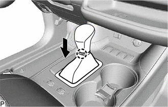
Disengage the claw and disconnect the shift hole cover sub-assembly as shown in the illustration.
-
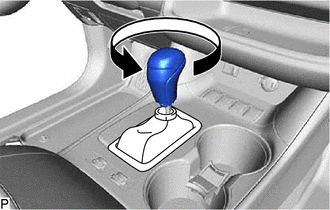
Turn the shift lever knob sub-assembly counterclockwise and remove it.
-
-
REMOVE FRONT PANEL GARNISH LH
-
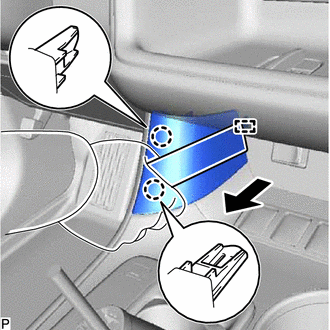
Using a moulding remover, disengage the 2 claws and guide, and remove the front panel garnish LH as shown in the illustration.
-
-
REMOVE FRONT PANEL GARNISH RH
-
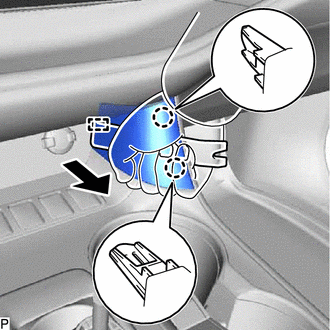
Using a moulding remover, disengage the 2 claws and guide, and remove the front panel garnish RH as shown in the illustration.
-
-
REMOVE NO. 1 CONSOLE UPPER PANEL GARNISH
-
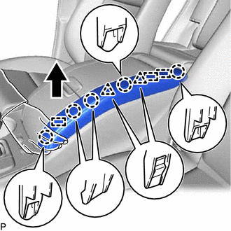
Disengage the 5 claws, 2 clips and 3 guides, and remove the No. 1 console upper panel garnish as shown in the illustration.
-
-
REMOVE NO. 2 CONSOLE UPPER PANEL GARNISH
-
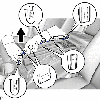
Disengage the 5 claws, 2 clips and 3 guides, and remove the No. 2 console upper panel garnish as shown in the illustration.
-
-
REMOVE UPPER CONSOLE PANEL SUB-ASSEMBLY
-
Move the shift lever to N.
-
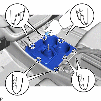
Disengage the 5 claws and 2 clips as shown in the illustration.
-
Disconnect the connector and remove the upper console panel sub-assembly.
-
-
REMOVE REAR CONSOLE LOWER BOX
-
Disengage the 6 claws and 2 guides, and remove the rear console lower box as shown in the illustration.
-
-
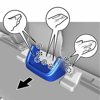
REMOVE CONSOLE BOX HOLE COVER
-
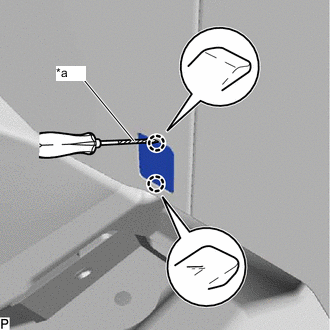
*a Protective Tape Using a screwdriver with its tip wrapped with protective tape, disengage the 2 claws and remove the console box hole cover.
Tech Tips
Use the same procedure for the RH side and LH side.
-
-
REMOVE CONSOLE BOX ASSEMBLY
-
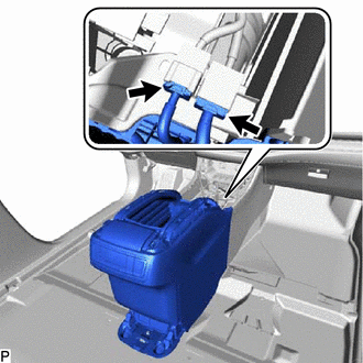
Disconnect the 2 connectors.
-
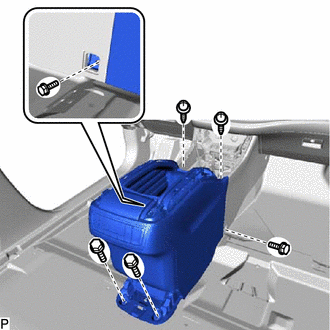
Remove the 4 bolts and 2 screws.
-
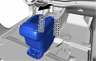
Disengage the 8 guides and remove the console box assembly as shown in the illustration.
-