INSTRUMENT PANEL SAFETY PAD INSTALLATION
PROCEDURE
-
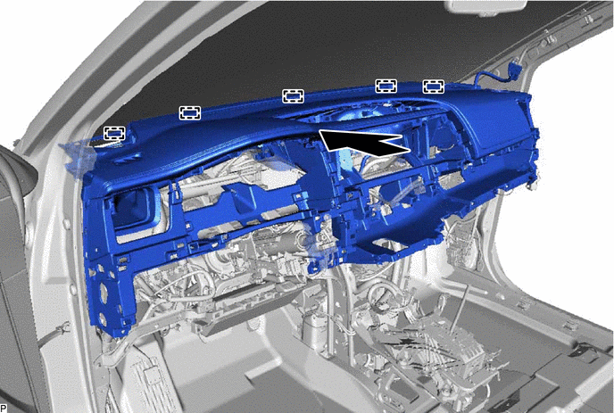
INSTALL INSTRUMENT PANEL SAFETY PAD SUB-ASSEMBLY
-
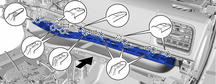
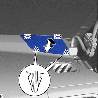
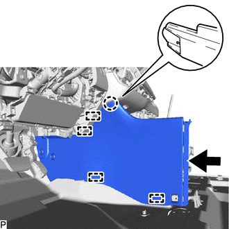
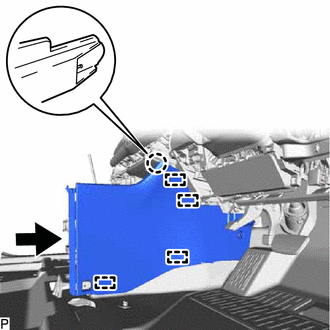
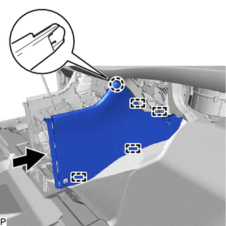
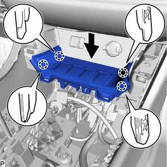
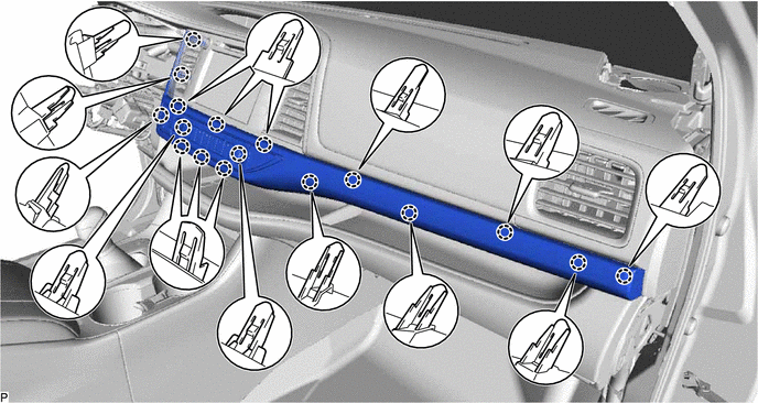
Engage the 5 guides to temporarily install the instrument panel safety pad sub-assembly as shown in the illustration.
Note
-
Do not damage the instrument panel safety pad sub-assembly.
-
Do not allow the wire harnesses to interfere with the surrounding parts.
-
-
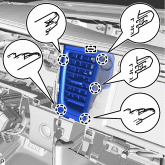
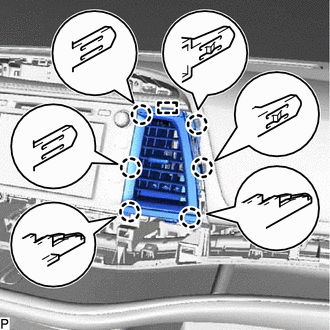
Install the instrument panel safety pad sub-assembly with the 6 bolts <C>, 2 bolts <A> and nut <E>.
- Torque:
- Bolt <A>
- 20 N*m { 204 kgf*cm, 15 ft.*lbf }
-
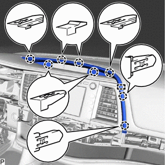
Install the 2 clips.
-
Engage each clamp.
-
Install the screw <D>.
-
Connect each connector.
-
Engage the 2 claws to connect the room temperature sensor.
-
-
CONNECT NO. 2 INSTRUMENT PANEL WIRE
-
INSTALL CENTER LOWER INSTRUMENT PANEL FINISH PANEL
-
Connect each connector.
-
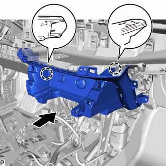
Engage the 2 claws as shown in the illustration.
-
Install the center lower instrument panel finish panel with the 2 bolts <C>, 2 screws <D> and 2 nuts <E>.
-
-
INSTALL NO. 1 SWITCH HOLE BASE
-
w/o Smart Key System:
-
Engage the 4 claws to install the No. 1 switch hole base.
-
-
w/ Smart Key System:
-
Connect the connector.
-
Engage the 4 claws to install the No. 1 switch hole base.
-
-
-
INSTALL NO. 2 INSTRUMENT PANEL REGISTER ASSEMBLY
-
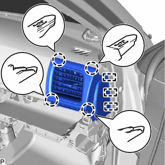
Engage the 3 guides and 4 claws to install the No. 2 instrument panel register assembly.
-
-
INSTALL INSTRUMENT PANEL FINISH PLATE
-
Engage the 3 guides and 6 claws as shown in the illustration.
-
Install the instrument panel finish panel with the 5 screws <D>.
-
-
INSTALL INSTRUMENT CLUSTER FINISH PANEL END
-
w/ Illumination
-
Connect the 2 connectors.
-
-
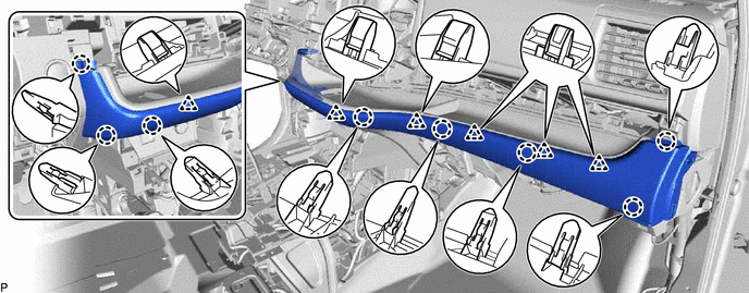
Engage the 3 guides and 11 claws to install the instrument cluster finish panel end as shown in the illustration.
-
-
INSTALL INSTRUMENT CLUSTER FINISH PANEL ORNAMENT
-
Engage the 8 claws and 6 clips to install the instrument cluster finish panel ornament.
-
-
INSTALL LOWER INSTRUMENT PANEL SUB-ASSEMBLY
-
Connect each connector.
-
Engage the guide and 3 clips as shown in the illustration.
-
Install the 2 bolts <B>.
-
Open the lower instrument panel sub-assembly door.
-
Install the lower instrument panel sub-assembly with the 3 screws <D>.
-
Close the lower instrument panel sub-assembly door.
-
-
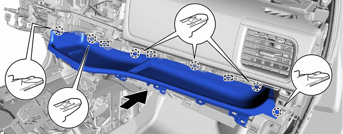
INSTALL NO. 2 INSTRUMENT PANEL UNDER COVER SUB-ASSEMBLY
-
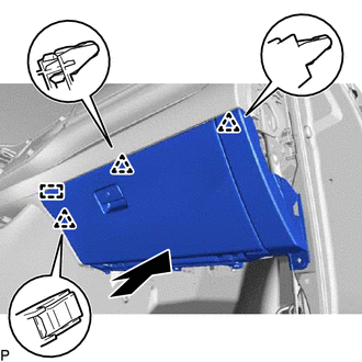
Engage the 2 guides and 4 claws to install the No. 2 instrument panel under cover sub-assembly.
-
-
INSTALL INSTRUMENT PANEL FINISH PANEL END RH
-
w/ Airbag Cut Off Switch:
-
Connect the connector.
-
-
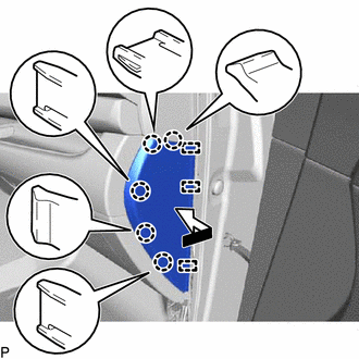
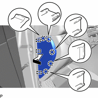
Engage the 3 guides and 5 claws to install the instrument panel finish panel end RH as shown in the illustration.
-
-
INSTALL FRONT NO. 2 SPEAKER ASSEMBLY (for RH Side)
-
INSTALL NO. 2 INSTRUMENT PANEL SPEAKER PANEL SUB-ASSEMBLY
-
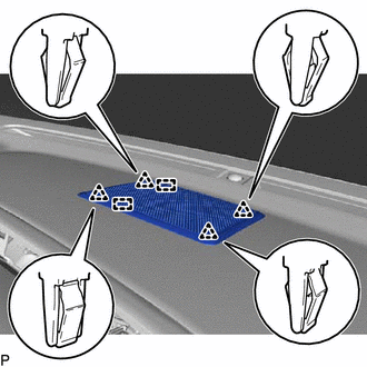
Engage the 2 guides and 2 clips to install the No. 2 instrument panel speaker panel sub-assembly as shown in the illustration.
-
-
INSTALL FRONT PILLAR GARNISH RH
-
INSTALL FRONT DOOR OPENING TRIM WEATHERSTRIP RH
-
INSTALL COWL SIDE TRIM SUB-ASSEMBLY RH
-
INSTALL FRONT DOOR SCUFF PLATE RH
-
INSTALL CONSOLE BOX INSERT
-
for LHD:
-
Engage the 4 guides and claw as shown in the illustration.
-
Install the console box insert with the 2 screws <D> and 2 clips.
-
-
for RHD:
-
Engage the 4 guides and claw as shown in the illustration.
-
Install the console box insert with the 2 screws <D> and clip.
-
-
-
INSTALL FRONT NO. 2 CONSOLE BOX INSERT
-
Engage the 4 guides and claw as shown in the illustration.
-
Install the front No. 2 console box insert with the 2 screws <D> and clip.
-
Engage the clamp.
-
-
INSTALL NO. 2 SWITCH HOLE BASE
-
Connect each connector.
-
Engage the 4 claws to install the No. 2 switch hole base as shown in the illustration.
-
-
INSTALL CONSOLE BOX ASSEMBLY
-
INSTALL CLOCK ASSEMBLY
-
INSTALL RADIO RECEIVER ASSEMBLY WITH BRACKET (for Radio and Display Type)
-
INSTALL NAVIGATION RECEIVER ASSEMBLY WITH BRACKET (for Navigation Receiver Type)
-
INSTALL NO. 4 INSTRUMENT PANEL REGISTER ASSEMBLY
-
Engage the guide and 5 claws to install the No. 4 instrument panel register assembly.
-
-
INSTALL NO. 3 INSTRUMENT PANEL REGISTER ASSEMBLY
-
Engage the guide and 6 claws to install the No. 3 instrument panel register assembly.
-
-
INSTALL CENTER UPPER INSTRUMENT CLUSTER FINISH PANEL
-
Engage the guide and 8 claws to install the center upper instrument cluster finish panel.
-
-
INSTALL CENTER INSTRUMENT CLUSTER FINISH PANEL WITH AIR CONDITIONING CONTROL ASSEMBLY
-
Connect the connector.
-
Engage the connector clamp.
-
Engage the 17 claws to install the center instrument cluster finish panel with air conditioning control assembly.
-
-
INSTALL FRONT NO. 3 SPEAKER ASSEMBLY (for 12 Speakers)
-
INSTALL NO. 1 SPEAKER OPENING COVER ASSEMBLY (for 12 Speakers)
-
Engage the 2 guides and 4 clips to install the No. 1 speaker opening cover assembly.
-
-
INSTALL NO. 1 INSTRUMENT PANEL REGISTER ASSEMBLY
-
Engage the 3 guides and 5 claws to install the No. 1 instrument panel register assembly.
-
-
INSTALL LOWER INSTRUMENT PANEL FINISH PANEL SUB-ASSEMBLY
-
Connect each connector.
-
Engage the 10 claws and 4 clips.
-
Install the lower instrument panel finish panel sub-assembly with the bolt <B>.
-
-
CONNECT HOOD LOCK CONTROL LEVER SUB-ASSEMBLY
-
Engage the 2 guides and claw to connect the hood lock control lever sub-assembly.
-
-
INSTALL NO. 1 INSTRUMENT PANEL UNDER COVER SUB-ASSEMBLY
-
Connect each connector.
-
Engage the connector clamp.
-
Engage the guide, claw and clip.
-
Install the No. 1 instrument panel under cover sub-assembly with the 2 screws <D>.
-
-
INSTALL INSTRUMENT PANEL FINISH PANEL END LH
-
Engage the 3 guides and 5 claws to install the instrument panel finish panel end LH as shown in the illustration.
-
-
INSTALL FRONT NO. 2 SPEAKER ASSEMBLY (for LH Side)
-
INSTALL NO. 1 INSTRUMENT PANEL SPEAKER PANEL SUB-ASSEMBLY
-
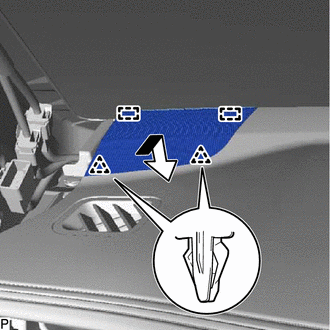
Engage the 2 guides and 2 clips to install the No. 1 instrument panel speaker panel sub-assembly as shown in the illustration.
-
-
INSTALL FRONT PILLAR GARNISH LH
-
INSTALL FRONT DOOR OPENING TRIM WEATHERSTRIP LH
-
INSTALL COWL SIDE TRIM SUB-ASSEMBLY LH
-
INSTALL FRONT DOOR SCUFF PLATE LH
-
INSTALL TURN SIGNAL SWITCH ASSEMBLY WITH SPIRAL CABLE SUB-ASSEMBLY
-
INSTALL UPPER STEERING COLUMN COVER
-
INSTALL LOWER STEERING COLUMN COVER
-
ALIGN FRONT WHEELS FACING STRAIGHT AHEAD
-
INSPECT AND ADJUST SPIRAL CABLE WITH SENSOR SUB-ASSEMBLY
-
INSTALL STEERING WHEEL ASSEMBLY
-
INSTALL HORN BUTTON ASSEMBLY
-
INSTALL COMBINATION METER ASSEMBLY
-
CONNECT CABLE TO NEGATIVE BATTERY TERMINAL
Note
When disconnecting the cable, some systems need to be initialized after the cable is reconnected.
-
CHECK STEERING WHEEL CENTER POINT
-
PERFORM DIAGNOSTIC SYSTEM CHECK
-
INSPECT SRS WARNING LIGHT