INSTRUMENT PANEL SAFETY PAD REMOVAL
PROCEDURE
-
PRECAUTION
Note
After turning the ignition switch off, waiting time may be required before disconnecting the cable from the negative (-) battery terminal. Therefore, make sure to read the disconnecting the cable from the negative (-) battery terminal notices before proceeding with work.
-
ALIGN FRONT WHEELS FACING STRAIGHT AHEAD
-
DISCONNECT CABLE FROM NEGATIVE BATTERY TERMINAL
CAUTION:
Wait at least 90 seconds after disconnecting the cable from the negative (-) battery terminal to disable the SRS system.
Note
When disconnecting the cable, some systems need to be initialized after the cable is reconnected.
-
REMOVE COMBINATION METER ASSEMBLY
-
REMOVE HORN BUTTON ASSEMBLY
-
REMOVE STEERING WHEEL ASSEMBLY
-
REMOVE LOWER STEERING COLUMN COVER
-
REMOVE UPPER STEERING COLUMN COVER
-
REMOVE TURN SIGNAL SWITCH ASSEMBLY WITH SPIRAL CABLE SUB-ASSEMBLY
-
REMOVE FRONT DOOR SCUFF PLATE LH
-
REMOVE COWL SIDE TRIM SUB-ASSEMBLY LH
-
DISCONNECT FRONT DOOR OPENING TRIM WEATHERSTRIP LH
-
Disconnect front door opening trim weatherstrip LH.
-
-
REMOVE FRONT PILLAR GARNISH LH
-
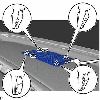
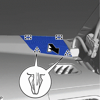
REMOVE NO. 1 INSTRUMENT PANEL SPEAKER PANEL SUB-ASSEMBLY
-
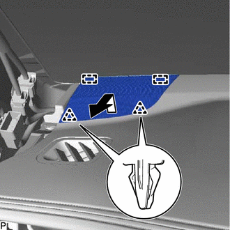
Disengage the 2 clips and 2 guides, and remove the No. 1 instrument panel speaker panel sub-assembly as shown in the illustration.
-
-
REMOVE FRONT NO. 2 SPEAKER ASSEMBLY (for LH Side)
-
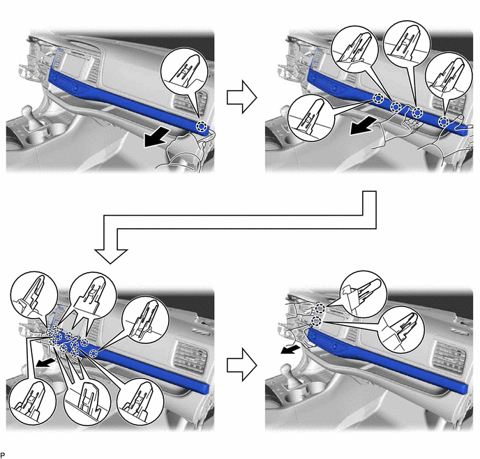
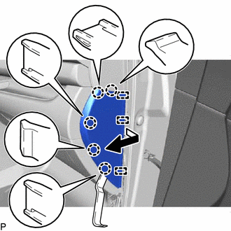
REMOVE INSTRUMENT PANEL FINISH PANEL END LH
-
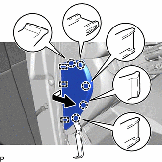
Using a moulding remover, disengage the 5 claws and 3 guides, and remove the instrument panel finish panel end LH as shown in the illustration.
-
-
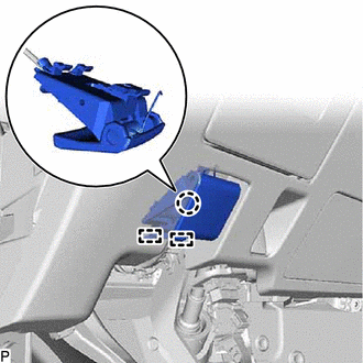
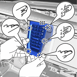
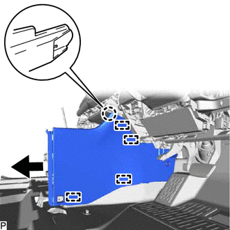
REMOVE NO. 1 INSTRUMENT PANEL UNDER COVER SUB-ASSEMBLY
-
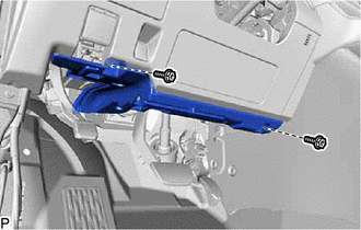
Remove the 2 screws <D>.
-
Disengage the claw, clip and guide.
-
Disengage the connector clamp.
-
Disconnect each connector to remove the No. 1 instrument panel under cover sub-assembly.
-
-
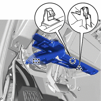
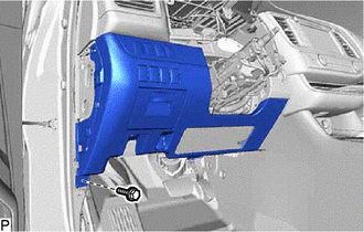
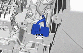
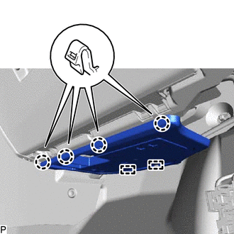
DISCONNECT HOOD LOCK CONTROL LEVER SUB-ASSEMBLY
-
Disengage the claw and 2 guides to disconnect the hood lock control lever sub-assembly.
-
-
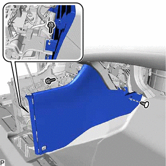
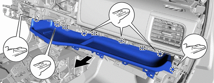
REMOVE LOWER INSTRUMENT PANEL FINISH PANEL SUB-ASSEMBLY
-
Remove the bolt <B>.
-
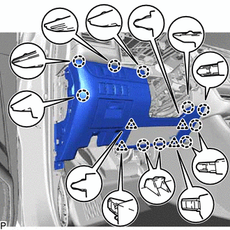
Disengage the 10 claws and 4 clips.
-
Disconnect each connector to remove the lower instrument panel finish panel sub-assembly.
-
-
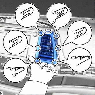
REMOVE NO. 1 INSTRUMENT PANEL REGISTER ASSEMBLY
-
Disengage the 5 claws and 3 guides to remove the No. 1 instrument panel register assembly.
-
-
REMOVE NO. 1 SPEAKER OPENING COVER ASSEMBLY (for 12 Speakers)
-
Using a moulding remover, disengage the 4 clips and 2 guides to remove the No. 1 speaker opening cover assembly.
-
-
REMOVE FRONT NO. 3 SPEAKER ASSEMBLY (for 12 Speakers)
-
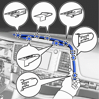
REMOVE CENTER INSTRUMENT CLUSTER FINISH PANEL WITH AIR CONDITIONING CONTROL ASSEMBLY
-
Using a moulding remover, disengage the 17 claws as shown in the illustration.
-
Disengage the connector clamp.
-
Disconnect the connector and remove the center instrument cluster finish panel with air conditioning control assembly.
-
-
REMOVE CENTER UPPER INSTRUMENT CLUSTER FINISH PANEL
-
Disengage the 8 claws and guide as shown in the illustration to remove the center upper instrument cluster finish panel.
-
-
REMOVE NO. 3 INSTRUMENT PANEL REGISTER ASSEMBLY
-
Disengage the 6 claws and guide as shown in the illustration to remove the No. 3 instrument panel register assembly.
-
-
REMOVE NO. 4 INSTRUMENT PANEL REGISTER ASSEMBLY
-
Disengage the 5 claws and guide as shown in the illustration to remove the No. 4 instrument panel register assembly.
-
-
REMOVE RADIO RECEIVER ASSEMBLY WITH BRACKET (for Radio and Display Type)
-
REMOVE NAVIGATION RECEIVER ASSEMBLY WITH BRACKET (for Navigation Receiver Type)
-
REMOVE CLOCK ASSEMBLY
-
REMOVE CONSOLE BOX ASSEMBLY
-
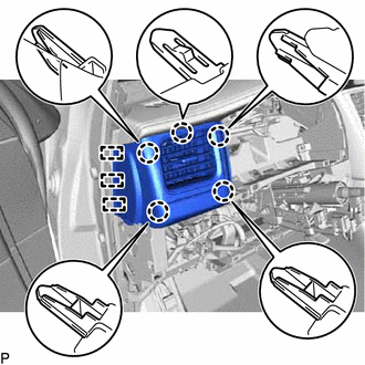
REMOVE NO. 2 SWITCH HOLE BASE
-
Disengage the 4 claws as shown in the illustration.
-
Disconnect each connector to remove the No. 2 switch hole base.
-
-
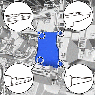
REMOVE FRONT NO. 2 CONSOLE BOX INSERT
-
Disengage the clamp.
-
Remove the 2 screws <D> and clip.
-
Disengage the claw and 4 guides, and remove the front No. 2 console box insert as shown in the illustration.
-
-
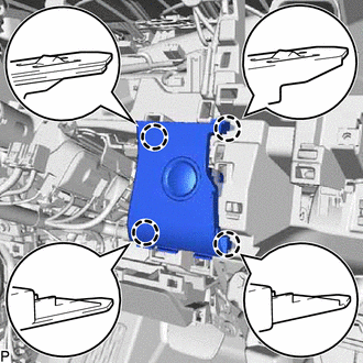
REMOVE CONSOLE BOX INSERT
-
for LHD:
-
Remove the 2 screws <D> and 2 clips.
-
Disengage the claw and 4 guides, and remove the console box insert as shown in the illustration.
-
-
for RHD:
-
Remove the 2 screws <D> and clip.
-
Disengage the claw and 4 guides, and remove the console box insert as shown in the illustration.
-
-
-
REMOVE FRONT DOOR SCUFF PLATE RH
Tech Tips
Use the same procedure as for the LH side.
-
REMOVE COWL SIDE TRIM SUB-ASSEMBLY RH
Tech Tips
Use the same procedure as for the LH side.
-
DISCONNECT FRONT DOOR OPENING TRIM WEATHERSTRIP RH
Tech Tips
Use the same procedure as for the LH side.
-
REMOVE FRONT PILLAR GARNISH RH
Tech Tips
Use the same procedure as for the LH side.
-
REMOVE NO. 2 INSTRUMENT PANEL SPEAKER PANEL SUB-ASSEMBLY
-
Disengage the 2 clips and 2 guides, and remove the No. 2 instrument panel speaker panel sub-assembly as shown in the illustration.
-
-
REMOVE FRONT NO. 2 SPEAKER ASSEMBLY (for RH Side)
Tech Tips
Use the same procedure as for the LH side.
-
REMOVE INSTRUMENT PANEL FINISH PANEL END RH
-
Using a moulding remover, disengage the 5 claws and 3 guides, and remove the instrument panel finish panel end RH as shown in the illustration.
-
w/ Airbag Cut Off Switch:
-
Disconnect the connector.
-
-
-
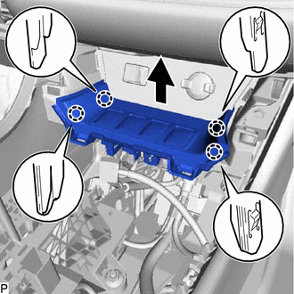
REMOVE NO. 2 INSTRUMENT PANEL UNDER COVER SUB-ASSEMBLY
-
Disengage the 4 claws and 2 guides to remove the No. 2 instrument panel under cover sub-assembly.
-
-
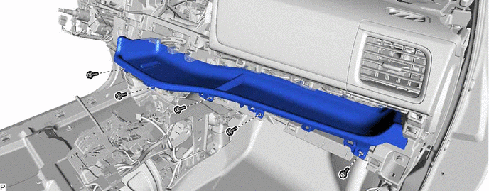
REMOVE LOWER INSTRUMENT PANEL SUB-ASSEMBLY
-
Open the lower instrument panel sub-assembly door.
-
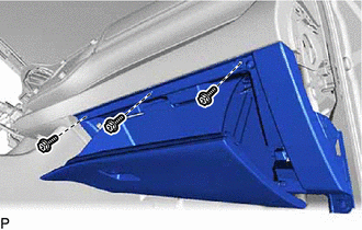
Remove the 3 screws <D>.
-
Close the lower instrument panel sub-assembly door.
-
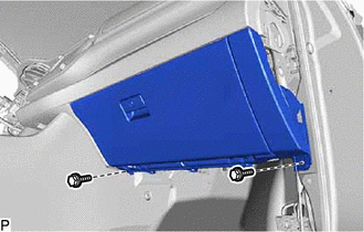
Remove the 2 bolts <B>.
-
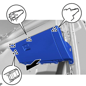
Disengage the 3 clips and guide as shown in the illustration.
-
Disconnect each connector and remove the lower instrument panel sub-assembly.
-
-
REMOVE INSTRUMENT CLUSTER FINISH PANEL ORNAMENT
-
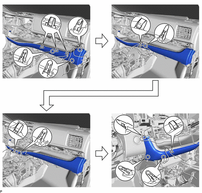
Disengage the 8 claws and 6 clips as shown in the illustration to remove the instrument cluster finish panel ornament.
-
-
REMOVE INSTRUMENT CLUSTER FINISH PANEL END
-
Disengage the 11 claws and 3 guides, and remove the instrument cluster finish panel end as shown in the illustration.
-
w/ Illumination
-
Disconnect the 2 connectors.
-
-
-
REMOVE INSTRUMENT PANEL FINISH PLATE
-
Remove the 5 screws <D>.
-
Disengage the 6 claws and 3 guides, and remove the instrument panel finish plate as shown in the illustration.
-
-
REMOVE NO. 2 INSTRUMENT PANEL REGISTER ASSEMBLY
-
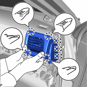
Disengage the 4 claws and 3 guides as shown in the illustration to remove the No. 2 instrument panel register assembly.
-
-
REMOVE NO. 1 SWITCH HOLE BASE
-
w/o Smart Key System:
-
Disengage the 4 claws to remove the No. 1 switch hole base.
-
-
w/ Smart Key System:
-
Disengage the 4 claws.
-
Disconnect the connector to remove the No. 1 switch hole base.
-
-
-
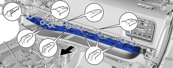
REMOVE CENTER LOWER INSTRUMENT PANEL FINISH PANEL
-
Remove the 2 bolts <C>, 2 screws <D> and 2 nuts <E>.
-
Disengage the 2 claws as shown in the illustration.
-
Disconnect each connector and remove the center lower instrument panel finish panel.
-
-
DISCONNECT NO. 2 INSTRUMENT PANEL WIRE
-
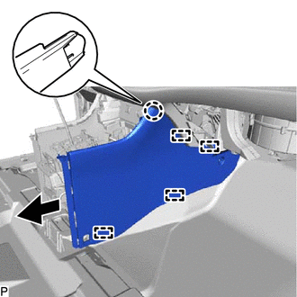
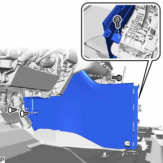
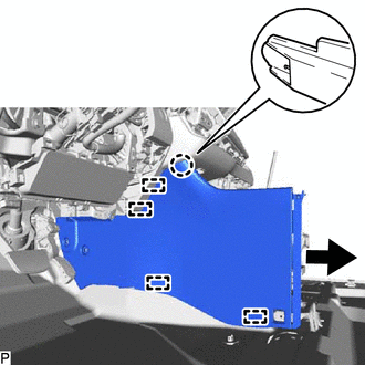
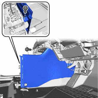
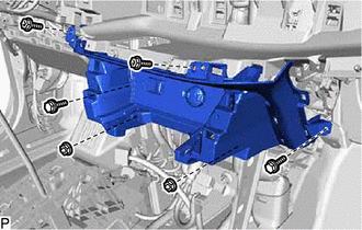
REMOVE INSTRUMENT PANEL SAFETY PAD SUB-ASSEMBLY
-
Disengage the 2 claws to disconnect the room temperature sensor.
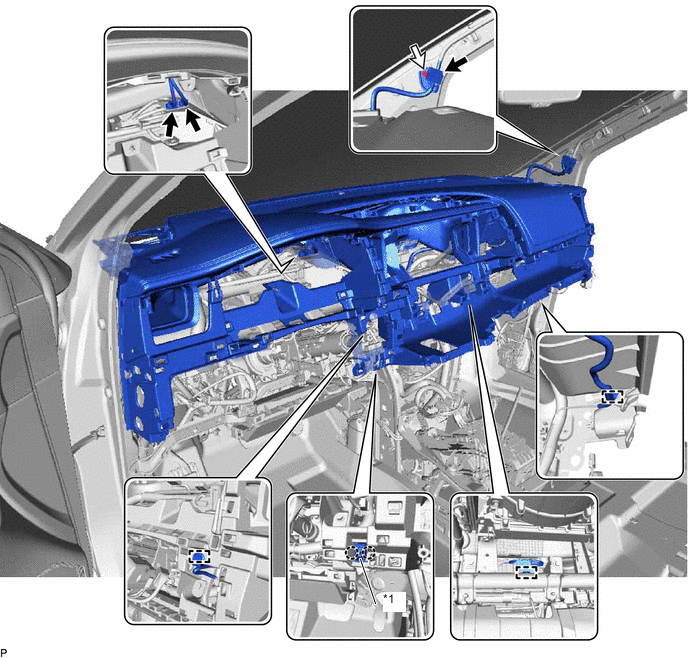
*1 Room Temperature Sensor - - -
Disconnect each connector.
-
Remove the screw <D>.
-
Disengage each clamp.
-
Remove the 6 bolts <C>, 2 bolts <A> and nut <E>.
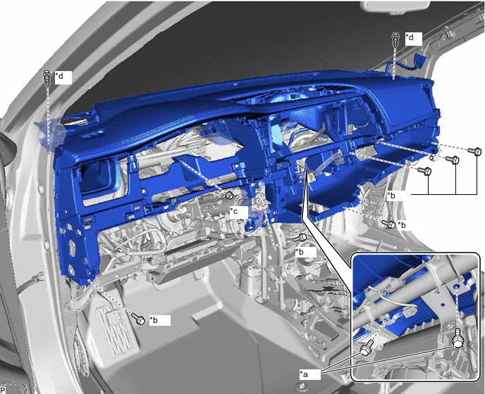
*a Bolt <A> *b Bolt <C> *c Nut <E> *d Clip -
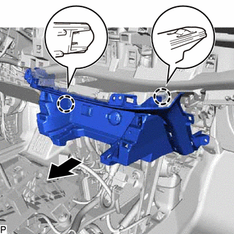
Remove the 2 clips.
-
Disengage the 5 guides and remove the instrument panel safety pad sub-assembly as shown in the illustration.
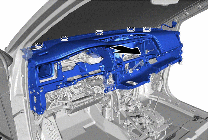
Note
-
Do not damage the instrument panel safety pad sub-assembly.
-
Do not allow the wire harnesses to interfere with the surrounding parts.
-
-