POWER OUTLET SOCKET REMOVAL
PROCEDURE
-
REMOVE CONSOLE BOX ASSEMBLY
-
REMOVE FRONT DOOR SCUFF PLATE LH
-
REMOVE COWL SIDE TRIM SUB-ASSEMBLY LH
-
DISCONNECT FRONT DOOR OPENING TRIM WEATHERSTRIP LH
-
REMOVE INSTRUMENT PANEL FINISH PANEL END LH
-
REMOVE NO. 1 INSTRUMENT PANEL UNDER COVER SUB-ASSEMBLY
-
DISCONNECT HOOD LOCK CONTROL LEVER SUB-ASSEMBLY
-
REMOVE LOWER INSTRUMENT PANEL FINISH PANEL SUB-ASSEMBLY
-
REMOVE CENTER INSTRUMENT CLUSTER FINISH PANEL WITH AIR CONDITIONING CONTROL ASSEMBLY
-
REMOVE NO. 2 SWITCH HOLE BASE
-
REMOVE FRONT NO. 2 CONSOLE BOX INSERT
-
REMOVE CONSOLE BOX INSERT
-
REMOVE FRONT DOOR SCUFF PLATE RH
Tech Tips
Use the same procedure as for the LH side.
-
REMOVE COWL SIDE TRIM SUB-ASSEMBLY RH
Tech Tips
Use the same procedure as for the LH side.
-
DISCONNECT FRONT DOOR OPENING TRIM WEATHERSTRIP RH
Tech Tips
Use the same procedure as for the LH side.
-
REMOVE INSTRUMENT PANEL FINISH PANEL END RH
-
REMOVE NO. 2 INSTRUMENT PANEL UNDER COVER SUB-ASSEMBLY
-
REMOVE LOWER INSTRUMENT PANEL SUB-ASSEMBLY
-
REMOVE INSTRUMENT CLUSTER FINISH PANEL ORNAMENT
-
REMOVE CENTER LOWER INSTRUMENT PANEL FINISH PANEL
-
REMOVE NO. 1 POWER OUTLET SOCKET ASSEMBLY
-
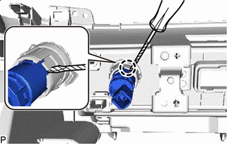

Protective Tape Using a screwdriver, disengage the claw and remove the No. 1 power outlet socket assembly as shown in the illustration.
Tech Tips
Tape the screwdriver tip before use.
-
-
REMOVE NO. 1 POWER OUTLET SOCKET COVER
-
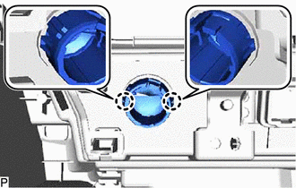
Disengage the 2 claws and remove the No. 1 power outlet socket cover.
-