BLOWER UNIT REASSEMBLY
PROCEDURE
-
INSTALL DRAIN COOLER HOSE
-
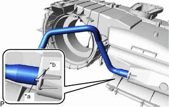
*a Hose Notch *b Blower Case Assembly Rib Align the hose notch with the blower case assembly rib as shown in the illustration and install the drain cooler hose.
-
-
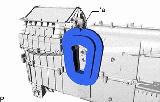
INSTALL BLOWER DAMPER SERVO SUB-ASSEMBLY
-
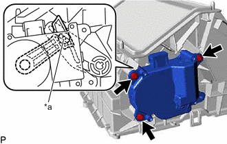
*a Link Connect the link of the blower damper servo sub-assembly to the link of the upper blower case as shown in the illustration.
-
Install the blower damper servo sub-assembly with the 3 screws.
-
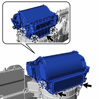
Engage the 4 claws to install the upper blower case.
-
Install the 3 screws.
-
-
INSTALL BLOWER MOTOR WITH FAN SUB-ASSEMBLY
-
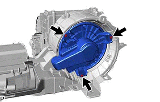
Install the blower motor with fan sub-assembly with the 3 screws.
Note
Do not install the blower motor with fan sub-assembly if it has been dropped or subjected to a severe impact.
-
-
INSTALL AIR REFINER ELEMENT
-
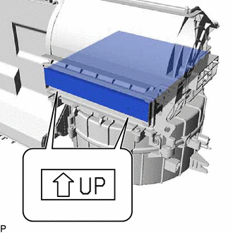
Install the air refiner element as shown in the illustration.
Note
Install the air refiner element with its UP mark oriented in the correct direction.
-
-
INSTALL AIR FILTER COVER PLATE
-
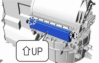
Engage the 2 claws to install the air filter cover plate as shown in the illustration.
Note
Install the air filter cover plate with its UP mark oriented in the correct direction.
-
-
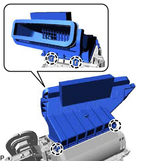
INSTALL NO. 1 COOLING UNIT PACKING
-
Remove any remaining No. 1 cooling unit packing from the blower assembly.
-
Remove the release paper from a new No. 1 cooling unit packing.
-
*a Notch Install the No. 1 cooling unit packing with the notch facing up as shown in the illustration.
-
-
INSTALL NO. 1 AIR DUCT SUB-ASSEMBLY
-
Engage the 4 claws to install the No. 1 air duct sub-assembly.
-